8 Foot Pedals
To get realistic action from the airplane or race car steering wheels (see
chapters 2 and 6) you need to use foot pedals with them. But the need for
foot pedals goes beyond making games more enjoyable. Several of the most
important aspects of flying and driving involve the coordination of hand
and foot movements. You can't use the power of the computer to learn to fly
or drive until you can practice these essential coordination skills.
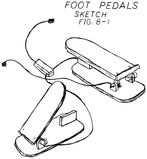
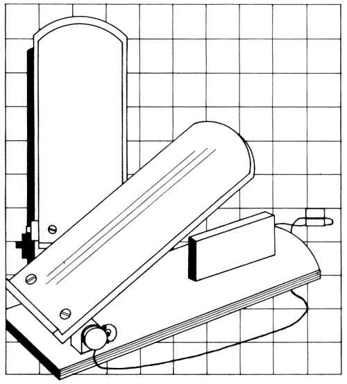
Fig.8-1. Sketch
These skills are critical in dangerous situations, such
as landing a light plane in strong crosswinds or recovering from a skid on
an icy bridge. With the steering wheels, foot pedals, and appropriate software,
you can practice vital responses in a simulated but realistic environment.
You can learn to anticipate and prevent accidents and gain the confidence
you need to pass licensing tests.
At present there are no commercial programs that use
both steering wheel game controls and foot pedals. As this kind of hardware
becomes available, commercial programs will certainly be modified to take
advantage of this new feature. Meanwhile, you can write your own. If you
can come up with even a modest program incorporating foot pedals you could
undoubtedly get it published as an article in a magazine. The steering wheel/foot
pedal combinations add such realism to flight and traffic simulations that
we are certain software development will proceed at a rapid pace.
The program we used to test the foot pedal prototypes
was International Grand Prix by Richard Orban, from Riverbank Software, Inc.
This program uses one paddle for the race car steering wheel and one pushbutton
for the accelerator/brake. When this program is used with the race car steering
wheel (chapter 6), the wheel controls the steering and the horn button controls
acceleration and braking. This is a vast improvement over a conventional
paddle in terms of feel and realistic action, but we all know that you don't
brake an automobile by honking the horn.
The prototype foot pedals were originally designed with
two pots and no pushbuttons. To use a foot pedal with the International Grand
Prix program we added a simple microswitch and a second cable and plug (see
figure 8-1). Now the car accelerates when you move the foot pedal forward
and brakes when you move it back. This is one step closer to real driving.
CONSTRUCTION
This is the easiest project to build in the entire book. It is a good exercise
for the home or school woodshop, and the materials are inexpensive and readily
obtainable. All the wood parts are 1/2-inch fir plywood except the heel rest,
which is hardwood scrap. You can complete this project using only hand tools,
but a table or radial arm saw will speed your work.
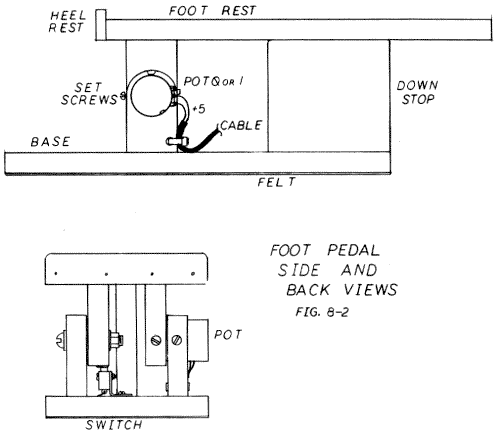
Figure 8-2 shows side and back views of a completed foot
pedal. The left and right units are identical, so remember to make enough
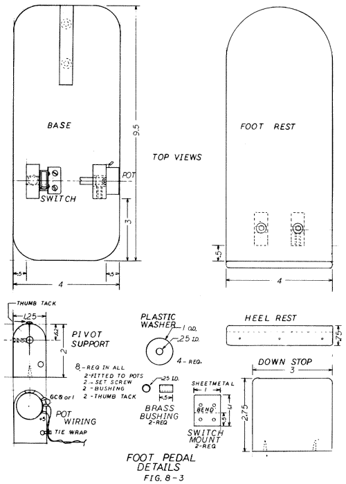
parts for two units. Figure 8-3 gives you details of the separate parts and
a top view of both the base and the foot rest.
The eight pivot supports (figure 8-3) require careful
attention. Two are simple pieces of plywood with 1/4-inch holes and a thumbtack
at one end. The holes in two more supports are lined with brass bushings
(1/4-inch ID). Another two supports have a 1/4-inch hole for the pot shaft
and a drilled and tapped hole for a set screw. The last two supports are
drilled out for the pot mounting bushing (usually 3/8-inch), tapped for a
set screw, and notched for the spin prevention tab on the pot.
After cutting out the plywood and hardwood pieces, round
the corners and edges with a rasp or saber saw and sand all parts smooth.
A Screw Mate drill bit is ideal for drilling the screw holes. Assemble the
bases with 1-inch x #8 flathead screws and carpenter's glue. Then assemble
the pots, upper pivot supports, and bolts. Attach the foot board to the upper
pivot supports with the same size screws. Now take the entire unit apart
and finish all wood parts with a bright-colored oil-based enamel.
If you are installing the switch feature that lets the
foot pedal act as one pushbutton for the International Grand Prix program,
you will need a small sheet metal switch mount (see figure 8-2). Using hand
shears, cut this out of galvanized steel, aluminum, or brass. Drill the top
two holes in the metal to suit the switch and the bottom two for 1/2-inch
x #6 panhead screws. For the prototypes we used a submini lever switch. The
switch and the small mounting nuts and bolts were purchased at Radio Shack.
Hold the sheet metal with vise grip pliers or in a bench vise while drilling
so that it won't spin and cut your fingers. It is best to make the mount
a little short, then move it up into position by shimming under it with thin
cardboard, wood, metal, or plastic. The thumbtack shown in figure 8-2 should
throw the switch when your foot is in a comfortable position, in the middle
of the pedal's range of movement.
The 1/4-inch bolts that form half the turning axis must
have flat washers where the bolthead and nut touch the wood, and a plastic
washer between the two wood parts. After final assembiy, lock the nut by
applying Loctite, Super Glue, or fingernail polish to the threads.
ELECTRICAL WIRING
The foot pedal prototypes were wired for two separate game control arrangements.
One arrangement has two foot pedals, each with one pot and no push button.
The second arrangement has a single pushbutton on one foot pedal and was
designed especially for playing International Grand Prix.
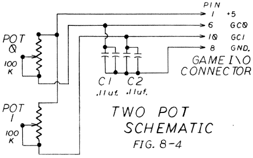
Figure 8-4 is the schematic for the two-pedal version.
The pots have short shafts (7/8-inch) and are mechanically rugged. They do
not turn through a full 300 degrees, so their maximum values must be about
four times the normal paddle pot values. If you use lower value pots, correction
capacitors C1 and C2 will be needed. For the prototypes, 100K pots and correction
caps were used. These caps were placed on a small piece of printed
circuit board and encased in a foam block at the place where the cables from
the two pedals come together (see figure 8-1). If you use correction caps
you will have to run the Correction Cap Calculation program from the software
chapter to work out their values.
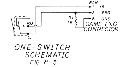
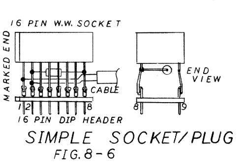
The circuit for the single-pedal version is shown in figure 8-5. The common and normally-open terminals of the switch are utilized. The pull-down resistor R1 is placed in the plug/socket (figure 8-6). Note that all the pins on the socket pass straight through; no pins are cut or bent. This circuit simply adds an additional pushbutton 0 to whatever paddle is plugged into its socket.
If you make up two foot pedals and add the switch circuit
(figure 8-5) with its separate plug/socket to the foot pedal with pot 1,
you will be ready to play any existing games and the future software that
will use all the foot pedal pots. While you are waiting for the new software,
you can plug the two-pedal version into the plug/socket of the switch version
and play your favorite single-paddle games with your feet.
FINISHING UP
You don't want the foot pedals to slide under your feet, so the bottoms should
be covered with something that grips the floor. If you will be placing them
on wood or linoleum, cut and fit some pieces from an old inner tube on them.
Cotton felt will grip a rug; for thicker carpets try incising shallow saw
cuts across the width of the bottom. Extra weight helps, so you can add extra
thicknesses of plywood to the baseboard or simply make the baseboard out
of 3/4-inch stock.
Perhaps you want the units to spring back to the open
position when there's no pressure on them. You could do this by attaching
rubber bands from the heel rest to the middle of the base, or by placing
a urethane foam block under the middle of the footrest. There are probably
many other different ways to spring-load these foot pedals. Use your imagination
and experience to come up with a solution that suits your needs.
| Parts List Foot Pedals |
||||||||||||||||||||||||||||||||||||||||||||||||||||||||||||||||||||
|
||||||||||||||||||||||||||||||||||||||||||||||||||||||||||||||||||||
|
Return to Table of Contents | Previous Chapter | Next Chapter