ATARI
DOS
OVERVIEW
The standard Atari Disk Operating System, DOS 2.0S, consists of four separate elements, ranked as follows in order of their “visibility” to the average DOS user.
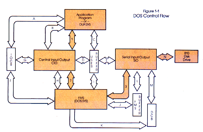
1. DUP — Disk Utility PackageIt is helpful to understand the entire Input/Output (I/O) process. While this book is intended to give detailed information on the workings of FMS, this overview will attempt to at least show how the four elements of DOS are connected. To this end, we would first call your attention to Figure 1. This figure is, itself, an overview of the entire Atari I/O system, including indications as to how and where data and control flows between the various elements thereof. Figures 1-1 through 1-4 show “close-ups” of portions of this diagram as they relate to the four elements of DOS.
2. CIO — Central Input/Output
3. FMS — File Management System
4. SIO — Serial Input/Output
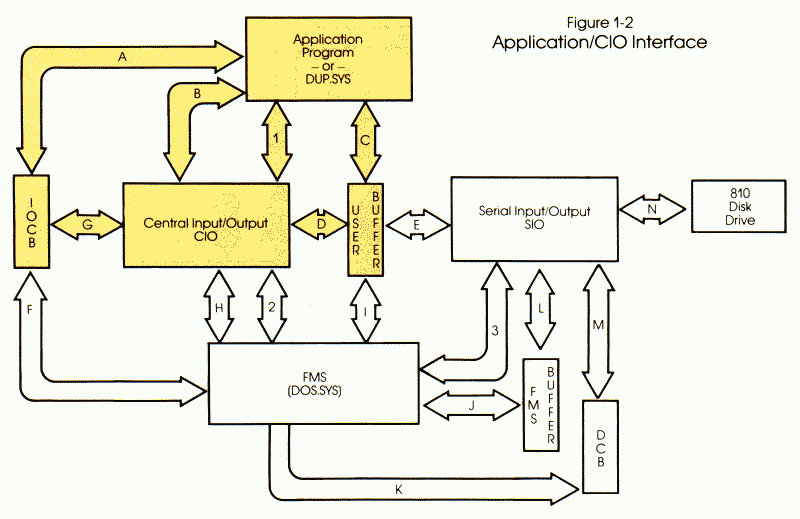
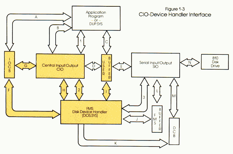
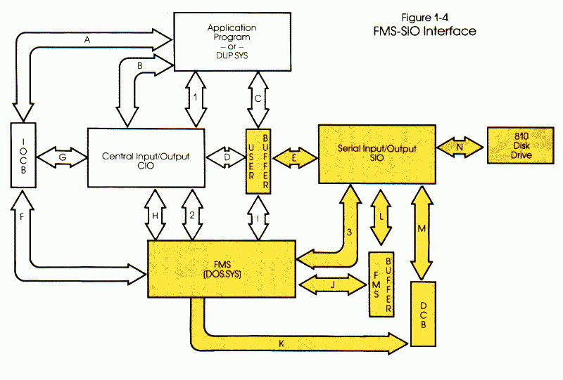
In these figures, the rectangular boxes represent system elements, and are appropriately labeled. The wide, lettered arrows represent the flow of data (via buffers, control blocks, or even registers) between the various elements. The narrow, numbered arrows show how and where control, and control information, is transferred.
1-1. Disk Utility Package
DUP (which shows as “DUP.SYS” in a disk directory listing) is the most
obvious and visible element of Atari DOS. DUP's function is to provide
the user with keyboard access to the various file management functions
in FMS. It does so via the menu which is displayed when, for example, the
user keys “DOS” from BASIC. Actually, the menu offers several options which
are not directly a part of the FMS (e.g., copy and duplicate files). Refer
to the Atari Disk Operating System II Reference Manual (part number C016347) for more information.
DUP is not an integral part of FMS. DUP may
be relatively easily replaced with a program of the user's choice. In fact,
our own OS/A + does exactly that: instead of a menu, the user is given
a command-driven keyboard interface to the other elements of DOS.
DUP is not even a privileged portion of DOS
(excepting, perhaps, for needing to know a little of the internals of FMS
when it performs a Duplicate Disk function). Any user application program
(and that includes Atari BASIC, BASIC A +, EASMD, and many, many more)
interacts the same way DUP does. Figure 1-1 shows the “proper” flow of
control in DOS. Note that DUP transfers control only to CIO, which, in
turn, transfers control to FMS and thence to SIO. An application program
which maintains this protocol should he able to perform correctly in any
Atari system, regardless of the revision of the OS ROMs and/or FMS.
Of course, control is not the only thing which
DUP must transfer. It must also tell CIO where its data is and what to
do with it. Refer to Figure 1-2 for a diagram of the complete application/CIO
interface (again, it is labeled in this way because DUP is just another
application program as far as the rest of DOS is concerned). CIO always
expects an Input/Output Control Block (IOCB) and usually (i.e., for all
but the simplest operations) needs a buffer into or out of which it may
perform its operations.
1-2. Central Input/Output
CIO is actually the heart of the entire Atari Computer. It is less
than 800 bytes long and yet serves to handle virtually all the input and
output which takes place in the computer. CIO is a part of the Atari “OS
ROMs,” the 10K byte package which also houses the floating point routines,
the default character set, the interrupt handlers, and several device drivers.
The entire set of operations summarized in
Figure 1-2 is covered in detail in the Atari OS Manual (C01655) and will
he covered only briefly here. Readers of COMPUTE!
will also find some helpful material on this subject in issues #18 through
#21 (November, 1981, through February, 1982) in the “INSIGHT: ATARI” columns.
In order to allow easy control and data flow,
CIO is written to expect and provide for eight Input/Output Control Blocks
(IOCBs) which are used to pass the information needed to process the various
kinds of I/O requests. An application places the necessary command and
control information in an IOCB which it selects (data path A). If a buffer
is required, the application must provide one (data path C) and place its
address into the IOCB. When ready to execute the I/O command, the application
places the IOCB number (times 16) in the 6502's X-register (data path C)
and executes a JSR call to CIO (control path 1). Note that a few command
variations may pass data via the 6502's A-register, but we may consider
that simply a special case location of the user's buffer.
When CIO receives control, it examines the
information in the IOCB (and, for some operations, in the user buffer)
to determine what actions it is to perform. Generally, this action requires
the execution of a device handler routine.
A device handler (interchangeably known as
a device driver) is a system routine that performs I/O operations for a
specific device (or class of devices). Examples of device handlers include
the “P:” driver (the printer) and the “E:” driver (the screen/keyboard
editor). Figure 1-3 illustrates the interface between CIO and the various
device handlers. Note that FMS is simply another device handler as far
as CIO is concerned, having been given the name “D:”.
All device drivers are required to contain
a table of address pointers (known as the Device Vector Table) to various
specific routines within themselves, including a device OPEN routine, GET
CHARACTER routine, etc. The name of a device and the address of this table
is placed in CIO's Device Handler Table. When an application program makes
an I/O request to CIO for a specific device, CIO searches the Device Handler
Table for the given name and corresponding Device Vector Table address.
With the thus-located vector table, CIO can then call the appropriate device
handler routine (via a JSR, along control path two of Figure 1-3).
1-3. File Management System
As stated above, FMS is actually simply another device driver as far
as CIO is concerned. The control and data flows shown in Figure 1-3 are
equally valid for all device drivers in the Atari system. Note that many
of the drivers in the default (“as-shipped”) system reside entirely within
the so-called OS ROMs. Although it resides in RAM, what is somewhat unique
about FMS is that the Atari system initialization code contains a segment
of “boot” code which loads FMS into memory upon power-on.
FMS is the system device handler for all I/O
operations that specify the device name “D” (including “Dl:”, “D2:”, etc.).
In order to perform its functions, FMS examines the data in the specified
IOCB (data path F). It may also examine, read, or write data to or from
the user-supplied buffer (data path I). Data path H is used to pass the
IOCB-designator (again, via the X-register) and single-byte transfer data
(via the A-register).
FMS is called upon to perform a variety of
tasks, including all disk I/O, file renaming, protecting, deleting, etc.
Since the rest of this book consists of a listing of FMS along with detailed
explanations of all sections thereof, we will not now dwell on the inner
workings of FMS.
However, we do need to note that, in order
to perform its work, FMS must transfer data to and from the disk. FMS accesses
the disk drive via SIO, the fourth element of DOS.
1-4. Serial Input/Output
SIO is the name given to the component of DOS which drives and controls
the Atari serial I/O bus and the various peripherals (disk, printer, modem,
etc.) which are placed on that bus. Figure 1-4 illustrates the interface
between FMS and SIO, but it could just as well serve to show (for example)
how the printer driver talks to the various Atari printers.
The SIO is primarily driven by a request placed
in SIO's Device Control Block (DCB) by the device handler (data path K)
followed by a transfer of control (control path three) via a JSR. SIO uses
the information in the DCB (data path M) to determine what it needs to
do. If the DCB specifies a serial bus data transfer (as opposed to, for
example, a status request), then the address of the data buffer must also
be passed (via a field in the DCB). For example, the FMS buffer shown is
accessed via data paths J (from FMS) and L (from SIO).
Although SIO only understands the single system
DCB, the buffer specified may be located anywhere in memory. FMS takes
advantage of this to implement “burst I/O” (discussed in section 12), which
has SIO transferring data directly to or from the user's buffer (data path
E).
Since the actual disk data transfer occurs
in fact within the 810 disk drive and, since SIO communicates to the drive
via data path N, one might reasonably argue that the disk drive constitutes
a fifth component of DOS. However, because the disk drive functions are
preprogrammed in ROM, and because SIO implements the only method of accessing
the disk (as well as most other peripherals), then, for all practical purposes,
even machine language software may treat SIO as the last link in the I/O
chain on the Atari Computers.
Once again, we remind you to study Figure
1. In the following dissertation and dissection of FMS, we shall refer
to this chart often.


Return to Table of Contents | Previous Chapter | Next Chapter

