You've built the simple circuits in this book, tried out the programs that accompanied them, and you're ready for more. Now what?
Since you've done the work already, let's take a look at some more ways to put these circuits to work. Once you start thinking about it, you'll quickly find that there's a very wide range of possible applications for these circuits. And the circuits can even be expanded to perform additional, more complex functions. Here are just a few projects you can create with the circuits you've built.
A Two-Beam Digital Timer Circuit
To make a two-beam digital timer, you'll need two digital light sensors (see Chapter 7).
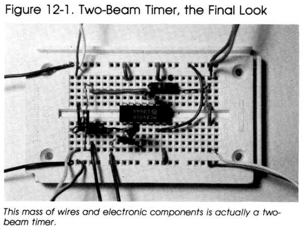
The two-beam timer begins timing when the first light beam is broken and stops timing when the second light beam is broken. A light sensor is required to monitor each of these light beams. The elapsed time between the two events (breaking the paths of the two light beams) is displayed on the computer's screen. This project is ideal for timing races. It may also be useful in classroom science experiments where the speed of an object must be measured by timing how long it takes for something to move from point A to point B.
You've already built one sensor-the second sensor can be put on the same solderless breadboard as your original circuit. Both light sensors operate in the same way, and the digital sensors even share one major circuit component, the 3900 op amp IC. The 3900 IC has four operational amplifiers (op amps) built in. Each digital light sensor requires the use of one operational amplifier. The second sensor just uses one of the three unused op amps. In fact, you could build four digital light sensors using a single 3900 IC.
Figure 12-2 is the schematic diagram of the two-beam digital timer circuit. For a more reliable switch, infrared sources are recommended.
Assuming you have the first digital light sensor at hand (see Chapter 7), here's a list of additional parts you'll need to build this circuit.

|
Here's how to construct your two-beam digital timer. |
|||||||||||||||||||||
|
1. Take the solderless breadboard you used to
create the digital light sensor in Chapter 7. Make sure all the components
are still on the board and in their proper places. 2. Solder a 4-inch length of copper wire to pin 2 of the 9-pin plug. This wire will provide the computer with the digital signal from the second sensor. 3. Insert the other end of this wire into point J6 of the solderless breadboard. 4. Solder two wires to the middle and one of the outside leads of the 500K potentiometer. 5. The other end of the middle wire goes to point A2 of the breadboard. 6. The wire from the outside lead goes to location X2 of the board. 7. Solder wires to the emitter and collector of the TIL 414 infrared phototransistor. The wires should be long enough so that the phototransistor can be mounted properly. Insert the emitter and collector leads into points J2 and Y2 respectively. 8. Bridge the three additional resistors between the following sets of points: Resistor From To R1 (10K ohm) G2 G9 R3 (100K ohm) H9 H10 R4 (1K ohm) I6 I10 9. Make the following jumper wire connections (in addition to the jumpers which already exist on the digital light sensor solderless breadboard which you built in Chapter 7) to complete the hardware for the two-light-beam timer: Jumper From To 1 G14 X19 2 F2 E2 |
| Using the Two-Beam Timer |
|

|
Plug the 9-pin connector into control port 2 for
the Commodore 64/128, or into control port 1 for the Atari computers. To
use the timer, set the sensors so that the light detect is interrupted when
the object being timed passes them. Each sensor must be calibrated using
its own potentiometer. Program 12-1 monitors the two digital inputs to the computer from the sensors. When the first sensor is triggered by the passing object, it starts timing. When the object blocks the light to the second sensor, the program stops timing and displays the results. Program 12-1-Commodore 64/128 JF 10 FOR I=0TO1 KF 20 PRINT"TURN ON FLASHLIGHT AND ADJUST THE" XP 30 PRINT"POTENTIOMETER ";I+1;" TILL THE MESSAGE JUST" DR 40 PRINT"CHANGES FROM OFF TO ON" CR 50 PRINT:PRINT"PRESS X TO CONTINUE" PM 60 A$=CHR$(145) HM 70 A=PEEK(56320) DX 80 IF (A AND 2↑I) THEN PRINT "OFF" BE 90 IF (A AND 2↑I)=0 THEN PRINT "ON " JS 100 GET B$ HE 110 IF B$="X"THEN140 JA 120 PRINTA$A$ CR 130 GOTO70 AS 140 NEXT I BB 150 PRINT"BREAK BEAM 1 TO START TIMER” GM 160 REM CHECK DATA REGISTER TILL FIRS T SENSOR TRIGGERED MD 170 IF (PEEK(56320)AND(2↑0))=O THEN170 BH 180 REM START TIMER JD 190 TI$="000000" AG 200 REM CHECK DATA REGISTER TILL SECO ND SENSOR TRIGGERED EM 210 IF (PEEK(56320) AND(2↑1))=0 THEN2 10 KS 220 PRINT"TIME IS";TI/60;"SECONDS" Program 12-1-VIC-20 SH 10 FOR I=2TO3 KF 20 PRINT"TURN ON FLASHLIGHT AND ADJUST THE" XP 30 PRINT"POTENTIOMETER ";I+1;" TILL THE MESSAGE JUST" DR 40 PRINT"CHANGES FROM OFF TO ON" CR 50 PRINT:PRINT"PRESS X TO CONTINUE" PM 60 A$=CHR$(145) GB 70 A=PEEK(37137) DX 80 IF (A AND 2↑I) THEN PRINT "OFF" BE 90 IF (A AND 2↑I)=0 THEN PRINT "ON " JS 100 GET B$ HE 110 IF B$="X"THEN140 JA 120 PRINTA$A$ CR 130 GOTO70 AS 140 NEXT I BB 150 PRINT"BREAK BEAM 1 TO START TIMER” GM 160 REM CHECK DATA REGISTER TILL FIRST SENSOR TRIGGERED BM 170 IF (PEEK(37137)AND(2↑2))=0 THEN170 BH 180 REM START TIMER JD 190 TI$="000000" AG 200 REM CHECK DATA REGISTER TILL SECOND SENSOR TRIGGERED QC 210 IF (PEEK(37137) AND(2↑3))=0 THEN210 KS 220 PRINT"TIME IS";TI/60;"SECONDS" Program 12-1-Atari FL 110 REM TWO LIGHT SENSOR TIMER PROGRAM FJ 112 REM CALIBRATE BOTH SENSORS AI 115 FOR I=0 TO 1 KP 120 PRINT "TURN ON FLASHLIGHT AND ADJUST THE" BE 130 PRINT "POTENTIOMETER ";I+1;" TILL THE MESSAGE JUST" K0 140 PRINT "CHANGES FROM OFF TO ON BL 150 PRINT :PRINT "PRESS X TO CONTINUE" OB 155 FOR J=1 TO 1000:NEXT J BE 160 A=STICK (0) KK 162 IF I=1 THEN 174 0J 164 IF A=15 THEN PRINT "OFF" 0J 166 IF A=13 THEN PRINT "OFF" KO 168 IF A=14 THEN PRINT "ON " KF 170 IF A=12 THEN PRINT "ON " GN 172 GOTO 190 OK 174 IF A=15 THEN PRINT "OFF" OL 176 IF A=14 THEN PRINT "OFF" KO 178 IF A=13 THEN PRINT "ON " KG 180 IF A=12 THEN PRINT "ON " MC 190 REM CHECK IF X KEY PRESSED JM 200 IF PEEK(764)=22 THEN 220 GO 210 GOTO 160 NE 220 REM CLEAR LAST KEYSTROKE CN 230 POKE 764,255 BO 240 NEXT I MF 250 PRINT "BREAK BEAM 1 TO START TIMER" AO 260 REM CHECK FIRST SENSOR TILL TRIGGERED MN 270 IF STICK(0)<>13 THEN 270 IN 280 REM START TIMER OF 290 POKE 18,0:POKE 19,0:POKE 20,0 JE 300 REM CHECK SECOND SENSOR UNTIL TRIGGERED II 310 IF STICK(0)=14 THEN 320 GG 315 GOTO 310 BC 320 PRINT "TIME IS ";((PEEK(18)*255*255)+(PEEK(19)*255)+(PEEK(20)))/60;" SECONDS"
Download (Saved BASIC)
|
Light Switch
This project combines the analog light sensor from Chapter 5 with the electronic switch you built in Chapter 8. The analog light sensor detects the level of outside light. As night approaches, the computer detects the change in light conditions and turns on a light via the electronic switch. Near dawn, the sensor detects the increase in light, and the computer switches off the light. (Of course, other things, from dark clouds during the day to car headlights at night, may also activate the switch.)
|
|
The analog light sensor, a cadmium sulfide photocell,
is connected between pins 9 and 5 of the electronic switch's 9-pin plug.
Use leads long enough so that the sensor can be aimed easily. The electric
light is connected to the relay of the electronic switch across its normally
closed and common terminals (remember, the relay turns on as soon as you
plug the circuit into the computer's port). Be sure that the ratings of the
solderless breadboard or relay are not exceeded by the electric light. The
circuit is connected to control port 1 of your computer. |
|||||||||||||||
|
|
Program 12-2-Commodore 64/128 GX 10 PRINT "SET LIGHTING LEVEL TO SWITCH ON" EG 20 PRINT "PRESS X TO CONTINUE" RA 30 A=PEEK(36872) HR 40 GET B$ RR 50 IF B$="X" THEN70 XE 60 GOTO30 QG 70 REM HP 80 PRINT "SET LIGHTING LEVEL TO SWITCH OFF" PD 90 PRINT "PRESS X TO CONTINUE" AX 100 B=PEEK(36872) ES 110 GET B$ DF 120 IF B$="X" THEN140 EJ 130 GOTO100 MJ 140 PRINT "PRESS X TO START" FB 150 GET B$ HQ 160 IF B$="X" THEN180 PS 170 GOTO150 PR 180 REM CHECK IF LIGHT LEVEL LOWER THAN FIRST SETTING FK 190 IF PEEK(36872)<A THEN190 SP 200 REM SET DATA DIRECTION REGISTER FOR OUTPUT XG 210 POKE 37139,PEEK(37139)OR(2↑2) CC 220 REM SET OUTPUT LINE LOGIC LOW CG 230 POKE 37137,PEEK(37137)ANDNOT(2↑2) HQ 240 REM CHECK IF LIGHTING LEVEL HIGHER THAN SECOND SETTING FP 250 IF PEEK(36872)>B THEN250 HQ 260 REM SET OUTPUT LINE LOGIC HIGH RG 270 POKE 37137,PEEK(37137)OR(2↑2) DG 280 REM RESET DATA DIRECTION REGISTER FOR INPUT FB 290 POKE 37139,PEEK(37139)ANDNOT(2↑2) Program 12-2-VIC GX 10 PRINT "SET LIGHTING LEVEL TO SWITCH ON" EG 20 PRINT "PRESS X TO CONTINUE" HD 30 A=PEEK(54297) HR 40 GET B$ RR 50 IF B$="X" THEN70 XE 60 GOTO30 QG 70 REM HP 80 PRINT "SET LIGHTING LEVEL TO SWITCH OFF" PD 90 PRINT "PRESS X TO CONTINUE" MB 100 B=PEEK(54297) ES 110 GET B$ DF 120 IF B$="X" THEN140 EJ 130 GOTO100 MJ 140 PRINT "PRESS X TO START" FB 150 GET B$ HQ 160 IF B$="X" THEN180 PS 170 GOT0150 PR 180 REM CHECK IF LIGHT LEVEL LOWER THAN FIRST SETTING CM 190 IF PEEK(54297)<A THEN190 SP 200 REM SET DATA DIRECTION REGISTER FOR OUTPUT ED 210 POKE 56323,PEEK(56323)OR(2↑0) CC 220 REM SET OUTPUT LINE LOGIC LOW CJ 230 POKE 56321,PEEK(56321)ANDNOT(2↑0) HQ 240 REM CHECK IF LIGHTING LEVEL HIGHER THAN SECOND SETTING BE 250 IF PEEK(54297)>B THEN250 HQ 260 REM SET OUTPUT LINE LOGIC HIGH GD 270 POKE 56321,PEEK(56321)OR(2↑0) DG 280 REM RESET DATA DIRECTION REGISTER FOR INPUT ED 290 POKE 56323,PEEK(56323)ANDNOT(2↑0) Program 12-2-Atari LP 100 REM LIGHT SWITCH HO 110 REM FC 120 PRINT "SET LIGHT LEVEL TO SWITCH ON" FC 130 PRINT "PRESS X TO CONTINUE" DO 140 A=PADDLE(0) LO 150 REM CHECK IF X KEY PRESSED KG 160 IF PEEK(764)=22 THEN 180 GG 170 GOTO 140 NN 175 REM CLEAR LAST KEYSTROKE DB 180 POKE 764,255 HF 190 PRINT "SET LIGHTING LEVEL TO SWITCH OFF" FA 200 PRINT "PRESS X TO CONTINUE" DN 210 B=PADDLE(0) LM 220 REM CHECK IF X KEY PRESSED KD 230 IF PEEK(764)=22 THEN 260 GC 240 GOTO 210 NH 250 REM CLEAR LAST KEYSTROKE DA 260 POKE 764,255 EI 262 PRINT :PRINT "PRESS X TO START" LC 264 IF PEEK(764)=22 THEN 268 HD 266 GOTO 264 DI 268 POKE 764,255 LE 270 REM CHECK IF LIGHT LEVEL LOWER THAN FIRST SETTING JK 280 IF PADDLE(0)<A THEN 280 GD 290 REM SET DATA DIRECTION REGISTER FOR OUTPUT FM 300 POKE 54018,48 IL 310 POKE 54016,255 FJ 320 POKE 54018, 52 FL 330 REM SET DATA LINES LOGIC LOW CC 340 POKE 54016,0 PD 350 REM CHECK IF LIGHTING LEVEL HIGHER THAN SECOND SETTING JN 370 IF PADDLE(0)>B THEN 370 IO 380 REM SET DATA LINES LOGIC HIGH JD 390 POKE 54016, 255 AH 400 REM RESET DATA LINES FOR INPUT FO 410 POKE 54018,48 CB 420 POKE 54016,0 FL 430 POKE 54018,52
Download (Saved BASIC)
|
|||||||||||||||
|
|
Enter and run the appropriate version of Program
12-2. You'll be prompted to set the lighting condition which will indicate
that the switch is to turn on. Do this by exposing the analog light sensor
to the amount of light at which you want the light to turn itself on. While
the sensor is still exposed to this light level, press the X key on the
computer. The computer stores this level of light as a number and will turn
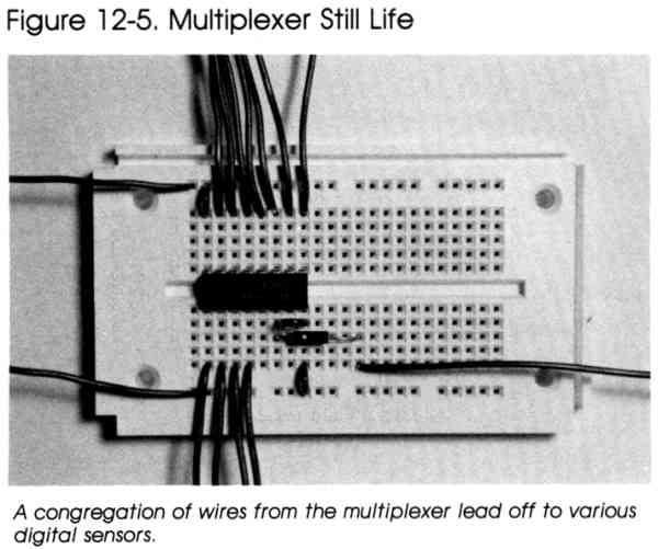
on the electric light when the sensor sees less than this amount of light. The program also prompts you to set the light off condition. After the electric light has been turned on, when this second light level (or more light) is present, the electric light is turned off. Using this circuit requires that the sensor be mounted near a window where it can detect outside light. Whatever you do, don't mount the sensor beneath the electric light you're controlling. Multiplexer Circuit A multiplexer circuit lets your computer monitor many digital input signals using its limited number of I/O lines. To make an eight-input multiplexer, you'll have to have these components: |
|||||||||||||||
|
|
|
| Follow these steps to put together your multiplexer: |
|
|
|
1. Insert the 74LS151 IC so that its pin 1 goes
into point F2 of the solderless breadboard, and its pin 9 into point E9. 2. Solder a 4-inch-long wire to pin 1 of one of the 9-pin plugs (for the Atari and VIC-20 versions, solder this wire to pin 6 of the single 9-pin plug required). This wire carries the selected data line's signal to the computer. 3. Connect the other end of this wire to point J12 of the breadboard. 4. The 1K ohm resistor bridges the points H12 to H6 of the board. (When building the Atari version, use a jumper wire in place of the resistor.) 5. Solder wires about four inches long to pins 1, 2, 3, 7, and 8 of the second 9-pin plug (in the case of the Atari and VIC versions, solder these wires to the same pins of the single 9-pin plug). 6. The wires from pins 7 and 8 provide the power to the circuit. Connect the wire from pin 7 to point X1, and the wire from pin 8 to location Y1 of the board. 7. The wires from pins 1, 2, and 3 insert into plug points D7, D8, and D9 respectively. These last three pins are used to select the data line signal "seen" by the computer. 8. Connect jumper wires as follows: Jumper From To 1 Y9 J9 2 X2 A2 3 G8 G9 Pins 1-4 and 12-15 of the 74LS151 IC are the input lines of the multiplexer. They can be connected to any sensor which provides an on/off signal. The sensors may be electronic (like the digital light sensor) or simply switches between the pins and ground. |
|
|
If you've built a multiplexer for the Commodore 64
or Commodore 128, the 9-pin plug with one wire attached is inserted into
control port 2. The other 9-pin connector plugs into control port 1. Since you used only one 9-pin plug for the Atari version, insert it into control port 2. Program 12-3 allows the circuit to monitor eight digital inputs. It outputs three digital signals to the multiplexer circuit, which tell it to route one of the input signals to a pin of the computer's I/O port. The program sequentially selects each of the eight input lines and checks its condition. (This is called polling.) If any of the eight inputs is at a logic low state, the computer prints out such a message on the screen. Program 12-3-Commodore 64/128 PK 10 PRINT "PRESS X TO EXIT PROGRAM" GM 20 REM SET DATA DIRECTION REGISTER FOR OUTPUT QJ 30 POKE 56322,255 RP 40 FOR I=0 TO 7 PE 50 REM SET DATA OUTPUT SR 60 POKE 56320,1 RG 70 IF (PEEK(56321)AND(2↑0))=0 THEN PRINT " SENSOR ";I RK 80 NEXT I EP 90 REM RESET DATA LINES FOR INPUT RQ 100 POKE 56322,0 ES 110 GET B$ BX 120 IF B$=”X" THEN END CP 130 GOTO30 Program 12-3-VIC-20 CM 10 PRINT" MONITORING SENSORS" HR 20 PRINT "PRESS X TO EXIT" DP 30 REM SET DATA DIRECTION REGISTER FOR OUTPUT QH 40 POKE 37139,(2↑2+2↑3+2↑4) GM 50 FOR I=0 TO 7 SP 60 REM SET DATA OUTPUT GH 70 POKE 37137,1*4 QC 80 IF (PEEK(37137)AND(2↑5))=0 THEN PRINT " SENSOR ";I JM 90 NEXT I GJ 100 POKE 37139,128 ES 110 GET B$ BX 120 IF B$="X" THEN END MQ 130 GOT040 GM 140 PRINT "TURN SWITCH OFF" Program 12-3-Atari ME 100 REM MULTIPLE INPUTS JB 110 PRINT "MONITORING SENSORS" ON 120 PRINT :PRINT" "PRESS X TO EXIT” FM 130 REM SET DATA DIRECTION REGISTER FOR OUTPUT FO 140 POKE 54018,48 CI 150 POKE 54016,7 FL 160 POKE 54018,52 OB 170 REM CYCLE THROUGH OUTPUT COMBINATION BA 180 FOR I=0 TO 7 DO 190 POKE 54016,1 AF 195 FOR J=1 TO 10:NEXT J EH 200 IF (STRIG(0)=0) THEN PRINT "SENSOR ";I LL 210 REM CHECK IF X KEY PRESSED KB 220 IF PEEK(764)=22 THEN 250 ON 230 NEXT I ON 235 GOTO 180 NO 240 REM CLEAR LAST KEYSTROKE CP 250 POKE 764,255 AL 260 REM RESET DATA LINES FOR INPUT SC 270 POKE 54018,48 CF280 POKE 54016,0 FP 290 POKE 54018,52
Download (Saved BASIC)
A Demultiplexer
Circuit |
|||||||||||||||
|
|
|
|||||||||||||||
|
|
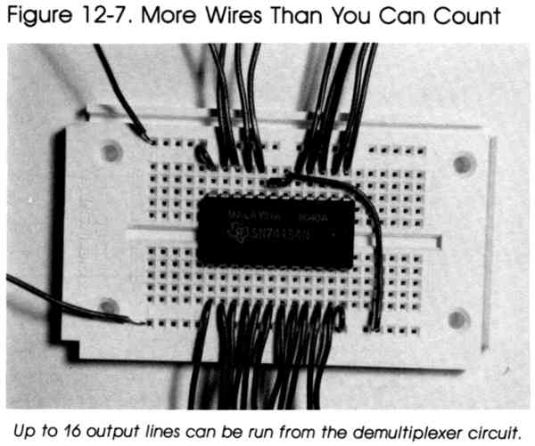
1. Insert the 74LS154 IC so that its pin 1 goes
into point G6 of the solderless breadboard, and its pin 24 into point C6. 2. Solder wires about four inches long to pins 1, 2, 3, and 4 of the 9-pin plug. These wires connect to the breadboard at these locations: Wire from Pin To Point 1 A7 2 A8 3 A9 4 A10 3. Solder two wires to pins 7 and 8 of the 9-pin plug. Connect the wire from pin 7 to point X1, and the wire from pin 8 to location Y1 of the board. 4. Solder wires for the digital output lines to these points on the breadboard: Digital Output Line To Point 0 J6 1 J7 2 J8 3 J9 4 J10 5 J11 6 J12 7 J13 Digital Output Line To Point 8 J14 9 J15 10 J16 11 A17 12 A16 13 A15 14 A14 15 A13 5. Connect jumper wires as follows: Jumper From To 1 Y17 J17 2 X6 A6 3 A12 Y20 4 B11 B12 |
|||||||||||||||
|
|
When you've finished, plug the 9-pin plug into control
port 2. The 74LS154 is interfaced to the computer using four lines from the control port. These four lines output the signals that select which of the output lines goes logic low. The outputs from the demultiplexer can be used to turn on electronic switches or other devices which require digital signals. The power for the demultiplexer circuit, as for the multiplexer, is obtained from pins 7 and 8 of the computer's control port. Sending signals to set an output line of the demultiplexer is very similar to sending the output required from the computer to select an input line of the multiplexer. The only difference is that four output lines from the computer are used instead of three. Try writing a program which will sequentially set each of the demultiplexer's output lines to a logic low state. You can verify your program using your logic probe. |
Return to Table of Contents | Previous Chapter | Next Chapter