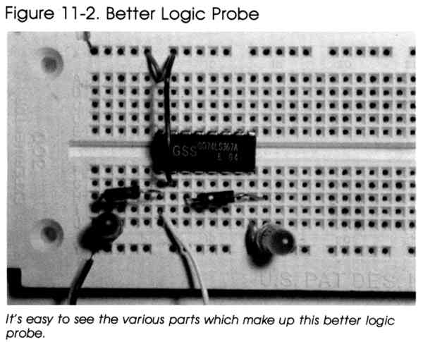
To experiment with digital logic circuits, you'll need a logic probe better than the simple one you built earlier. The logic probe illustrated here is capable of detecting both logic high and logic low states in a circuit. (If you're really serious about experimenting with digital circuits, you should definitely consider buying a commercial logic probe.)
To put together this more sophisticated logic probe, you'll need these components:

|
Here's how to put together the "better" logic probe: |
||||||||||||||||||||||||
|
1. Cut three pieces of stranded copper wire about
8 inches long and remove about 1/4 inch of insulation from each end. Attach
an alligator clip to one end of each of these wires. 2. Connect the other end of one wire to point Y1 of the solderless breadboard. This lead is the ground wire. 3. Insert one end of another wire, the +5-volt lead, to point X1 of the breadboard. 4. The third wire is the probe lead and is inserted into point I6 of the board. 5. Insert the 74LS367 IC into the breadboard so that its pin 1 goes into point F6, and its pin 9 goes into point E13. 6. Connect three jumper wires as follows: Jumper From To 1 G7 X7 2 J13 Y13 3 X5 A6 7. The 1K ohm resistors bridge the following points: Resistor From To 1 H2 H6 2 H7 H14 8. The red LED is mounted on the breadboard so that its cathode plugs into point Y2 and its anode into point J2. 9. The cathode of the green LED inserts into point Y14, while its anode plugs into point J14. |
||||||||||||||||||||||||
| |
Probing |

|
To use the logic probe, connect the ground wire and
+5-volt wire to the power supply ground and +5-volt terminals of the circuit
you're checking. Touch the probe lead to the point of the circuit you want
to check. If the green LED turns on, the point is at a logic low level, but
if the red LED lights, the point is at a logic high level. (If neither LED
lights, the point is neither at a logic high nor low state.) When the probe is touched to a logic high point of the circuit, current flows through the red LED, causing it to light. The probe is also connected to the enable input pin of the 74LS367 IC. When this pin is high, all the buffer outputs in the chip enter the high impedance state. Since the green LED is connected to the output of a buffer, it remains off. The green LED is effectively disconnected from the circuit since one of its leads is connected to the buffer output, which is acting like a very large resistor (open circuit). When the probe is touched to a logic low point of the circuit, no current flows through the red LED since both its leads are at the same voltage (ground). The low signal, however, enables the 74LS367 IC so that its buffers act normally. Since the buffer (whose output is connected to the green LED) input is attached to +5 volts, the green LED lights up. This happens because the output of the buffer is logic high, and as a result, a current flows through the green LED causing it to illuminate. Note that due to low current levels, the LEDs may be dim and difficult to see at times. This circuit is very handy for exploring and troubleshooting digital circuits. It's also a worthy candidate for "permanent" mounting on a printed circuit board, perhaps, as you'll probably use it often. |
Return to Table of Contents | Previous Chapter | Next Chapter