Notes & Discussion
|
1. Horizontal and vertical scrolling are good additions to graphics capabilities. They make displays easier and provide some effects that would be almost impossible to generate otherwise.
Scrolling is causing the display to appear to "roll by", so that when an object on the display comes into view, it moves across the screen and disappears on the other end. (The Atari coin-op games where you fly over enemy terrain, bombing targets that roll by underneath you, is an example of scrolling. These games could he implemented on the 400/800 using scrolling techniques.)
In order to have a display scroll, we must first send it to the screen in unmoved format, then move it, then send it again. This will cause the display to shift once. Repeatedly doing this causes a scrolling effect. All our displays, generated by ANTIC and CTIA, are stored in memory and sent to the display sixty times a second. So what we have to do is change display memory in such a way that it will cause the display on the screen to scroll.
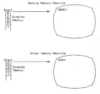
If the display memory is changed so that all information in it is copied 40 bytes up, in graphics 0, then on the next refresh the former top line will be replaced by the information from the line below it. (Lines are 40 bytes long, remember.) You have seen this effect when the Atari scrolls something up off the screen, as happens during a long listing. If we were to move the data in the display memory up just one byte, the screen would scroll to the left, for the contents of the second byte would now be displayed in the first byte's screen position, and so on down the screen. See Figure 12.
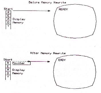
This is a good way to do scrolling if you are working in assembly language. The amount of data that must he moved, however, (960 bytes in graphics 0) is so large that it becomes impossible for Basic to do the job quickly enough. There is a way, however, to do scrolling from Basic without moving a large block of memory. Instead of having ANTIC look at the same place in memory for display memory data and moving that data around, let's just change where ANTIC looks and leave memory alone (see Figure 13). The Atari does not have a fixed unchangeable location in memory for display memory, unlike other machines. We can change where ANTIC looks for data with two POKES.
For example, if we were to tell ANTIC that screen memory started one byte down from where it really did, ANTIC would skip the first real byte of screen memory, and the screen would seem to scroll to the left. ANTIC would not know the difference, yet the screen would have horizontally scrolled. If we were to tell ANTIC the screen memory starts 40 bytes down from where it really does, the screen will scroll up. You can obtain some good demonstrations this way. Try program 5 to scroll the screen horizontally, program 6 to scroll it vertically, and program 7 to scroll it both ways. All these programs do is change the pointer ANTIC uses to find display memory. They are a good deal of fun to leave running in a computer store somewhere.
|
All this gives us is coarse horizontal/vertical scrolling. When we rewrite display memory, we shift characters 8 dots or 8 scan lines (in graphics 0). This is a long way to shift things on the screen, and we do not get smooth motion. The Atari computer has the ability to smooth out this scrolling process. You can shift the display the number of "fine" dots or lines you need to span the distance between coarse movements smoothly, a dot or a line at a time. You cannot scroll more than the distance between one coarse scroll using the fine scroll machinery. Compare it to the fine tuning on a television set; you cannot change channels with the control, but you can smooth out the gaps between channels. Fine scrolling is limited to 0-7 dots/lines in graphics 0 or 0-16 dots/lines in graphics 2.
On the Atari scrolling is only a positive value. You cannot scroll something down using the scrolling hardware; you must start with it scrolled fully up and then scroll it "less upwards" to achieve a downward effect. How much you wish to display scrolled is written into a certain memory location.
In order to make a smoothly scrolling vertical display, we would need to select our "coarse" vertical position with the display memory and ANTIC pointer, then select how many "fine" scan lines to scroll up from that position using the scroll register. Presumably we would increment the scroll register slowly from 0 to 7, moving the display up. When we reached 7, we would rewrite display memory or change ANTIC's pointer to get the eighth and final line. Then we would start over, incrementing our vertical scroll from 0 to 7, and continue until we were done. A downward scroll is not very different. Just move the scroll register from 7 to 0 and then rewrite memory.
The display list entry for a given display block must be modified to allow scrolling. If you write something to the scroll register, but do not change the display list, nothing happens.
20 START=PEEK(560)+256*PEEK(561)
30 REM ANTIC DISPLAY MEMORY POINTER
40 REM IS AT START+4 AND START+5
50 REM
100 X=PEEK(START+4)+256*PEEK(START+5)
110 PRINT "START OF DISP MEMORY=";X
200 FOR Y=X TO X+80
205 PRINT "POINTER=";Y
210 REM SPLIT Y UP INTO TWO BYTES
220 YHI=INT(Y/256)
230 YLO=Y-(YHI*256)
240 POKE START+4,YLO:POKE START+5,YHI
250 FOR DELAY=1 TO 20:NEXT DELAY
260 REM
270 NEXT Y
Program 5.
20 START=PEEK(560)+256*PEEK(561)
30 REM ANTIC DISPLAY MEMORY POINTER
40 REM IS AT START++4 AND START+5
50 REM
100 X=PEEK(START+4)+256*PEEK(START+5)
110 PRINT "START OF DISP MEMORY=";X
130 REM
140 REM SCROLL UP
200 FOR Y=X TO X+(40*20) STEP 40
210 GOSUB 1000
260 REM
270 NEXT Y
500 REM SCROLL DOWN
510 FOR Y=X+(40*20) TO X STEP -40
520 GOSUB 1000
530 NEXT Y
550 REM
600 REM SCROLL LEFT
610 FOR Y=X TO X+40
620 GOSUB 1000
630 NEXT Y
640 REM SCROLL RIGHT
650 FOR Y=X+40 TO X STEP -1
660 GOSUB 1000
670 NEXT Y
680 GOTO 140
990 REM CALCULATE HI, LOW BYTES
1000 YHI=INT(Y/256)
1010 YLO=Y-(YHI*256)
1030 POKE START+4,YLO:POKE START+5,YHI
1040 RETURN
Program 6.
20 START=PEEK(560)+256*PEEK(561)
30 REM ANTIC DISPLAY MEMORY POINTER
40 REM IS AT START+4 AND START+5
50 REM
100 X=PEEK(START+4)+256*PEEK(START+5)
110 PRINT "START OF DISP MEMORY=";X
130 REM
140 REM SCROLL UP
200 FOR Y=X TO X+(40*20) STEP 40
210 GOSUB 1000
260 REM
270 NEXT Y
500 REM SCROLL DOWN
510 FOR Y=X+(40*20) TO X STEP -40
520 GOSUB 1000
530 NEXT Y
540 GOTO 140
550 REM
990 REM CALCULATE HI, LOW BYTES
1000 YHI=INT(Y/256)
1010 YLO=Y-(YHI*256)
1030 POKE START+4,YLO:POKE START+5,YHI
1040 RETURN
Program 7.
Some details on how fine scrolling is implemented.
ANTIC normally displays a fixed number of scan lines per display block. For example, in graphics 0, it displays 8 scan lines. When we vertically scroll, ANTIC does not do this anymore. When ANTIC encounters the beginning of a "scrolled zone", a group of display list opcodes with vertical scroll modifiers, it treats the beginning and the end of the scrolled zone differently than it normally would to achieve the scrolling effect.
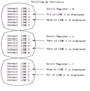
When ANTIC finds the first scroll marked display block, it does not display the normal number of scan lines for that block. It only displays the bottom "slices" of that display block, the exact number is determined by what is in the scroll register you have written to. Because the top display block is shortened, the display below that point moves up. For example, if there is a 4 in the scroll register, only scan lines 4,5,6 and 7 of the display block are shown, which are the lower slices of a character.
The display blocks in the middle of the scrolled zone (the ones with their vertical scroll modifiers set) are displayed normally, although their position is shifted up as a result of the first one having a short display block. When ANTIC reaches the end of the scrolled zone, it displays only the top few lines of the display block. If the scroll register had a 4 in it, ANTIC would only display lines 0, 1, 2, and 3; the top half of the characters. This is necessary to make the total number of scan lines in the scrolled area be the same. If the total should change, the display below the scrolled area would shift up and down with the scrolling, and it would not be limited to the zone indicated by the display list. Since the top and bottom blocks of the scroll area always have a total displayed amount of one display block, we get a fixed size scrolled zone, even though the displayed data varies. Also note that you "lose" one display block height, because the total of the two outer display blocks is now one display block height.
This is a strange way of doing things, but very effective. If you run program 8, you will see vertical scrolling in action. This program writes two separate vertical scrolled zones into the display list, then scrolls them using the register. When you run the program, you will note the size of the display shrinks by two display blocks. These are the "lost" scrolled display blocks. Note how the scrolled letters seem to disappear behind the fixed letters. They are not really disappearing, they are just not being plotted. (Figure 14).
5 VSCROLL=54277
10 START=PEEK(560)+256*PEEK(561)
20 REM *** PUT SOME DATA ONSCREEN.
30 GRAPHICS 0
25 FOR T=1 TO 24
35 PRINT "THIS IS LINE #";T
37 NEXT T
40 REM ** ALTER DISPLAY LIST TO V
45 REM ** IN TWO AREAS, 2 + 32 = 34
60 FOR Y=START+10 TO START+13
70 POKE Y,34
80 NEXT Y
81 FOR Y=START+17 TO START+20
82 POKE Y,34
83 NEXT Y
84 REM ** SCROLL UP
90 FOR Y=0 TO 7
100 POKE VSCROLL,Y
105 GOSUB 200
110 NEXT Y
115 REM *** SCROLL DOWN
120 FOR Y=7 TO 0 STEP -1
130 POKE VSCROLL,Y
135 GOSUB 200
140 NEXT Y
150 GOTO 90
160 REM ** SHORT DELAY LOOP
200 FOR T=1 TO 50:NEXT T
210 RETURN
Program 8.
Scroll Registers |
|
Name |
Address |
| Hex | Decimal |
| Vertical Scroll D405 | 57239 |
| Horizontal Scroll D404 | 57238 |
2. Load Memory Scan (LMS)
This introduction is nice to know about when you are starting out and is essential later on when you start creating complex displays.
When ANTIC first learns where display memory is, it takes the 16 bit memory address and stores it in an internal (ANTIC) register. When it would like some data from display memory, perhaps 40 bytes of character data for a line of graphics mode 0, ANTIC looks to this register to find out the current line of display memory. ANTIC fetches the byte at that location. It then increments this register by one each time it gets a byte to point at a new byte.
It is tricky, because this internal register is really only 12 bits long. The other 4 bits are latches which cannot count. That means that as ANTIC goes along, if it should hit a 4K boundary in absolute memory (a 1000 hex address point),it will start all over again at the beginning of the previous 4K section of memory. This problem causes extreme frustration, even at Atari. It is quite difficult to diagnose as it resembles other problems. It is also very commonplace. Do not let your display memory cross a 4K boundary without resetting the display memory register with the load memory scan (LMS) opcode modifier. Place the 16 bit value of the next display memory in the two following bytes, low byte first, then high byte. You have seen this instruction before. It is the 66 at the beginning of the graphics 0 display list we printed. The 66 is a 2 opcode (a graphics 0 instruction), with a 64, the LMS modifier, added to it. If you actually counted the 2's in the previous example, you would find only 23 2's; the 24th display block is taken care of by the "hidden" 2 in the 66 instruction.
|
This instruction also accounts for some of the graphics 8 display list instructions. Graphics 8 uses 7680 bytes of display memory. That is more than 4K (4096 bytes). The graphics 8 display list must have two or more LMS instructions to reset the memory address register inside ANTIC.
The display list itself cannot cross a 1K boundary for similar reasons. ANTIC's pointer to display memory is 16 bits long, but the top 6 bits are latches only; they cannot count. You must use the JMP ANTIC instruction to pass a 1K boundary in the display list. If you start getting bizarre display list results, check this. Follow the JMP instruction with the 16 bit address to continue executing the display list.
3. Display List Interrupts
Setting this bit in an ANTIC opcode (modifiers are nothing but top bits set in the opcodes) will cause the following actions:
I. A "memory" location on the ANTIC chip is checked. If the top bit is not set, the interrupt bit is ignored.
2. If it is set, ANTIC completes the display block where it found the interrupt, up until the beginning of the last line of the block.
3. The 6502 receives a "non-maskable interrupt" (very high priority) and is sent to the memory location whose address is written into 200 and 201 hex (512,513 decimal). At the memory location whose address you POKEd into 200, 201 Hex you should have an interrupt service routine which eventually returns the 6502 to what it was doing.
Display list interrupts are incredibly powerful tools to use in your display's construction. If we needed to get a large number of colors on the screen at the same time, we could use a display list interrupt to specify a color change to occur between two display blocks. When plotting the screen, every sixtieth of a second, the Atari would change a color register (and a plotted color) in mid-refresh. Using this capability requires knowledge of a 6502 assembler language.
Table of Contents
Previous Section: Display List Opcodes
Next Section: Basic and Color