Basic and Color
(Background for Display List Interrupts)
|
The Atari was designed to be able to create a wide variety of TV displays. The designers knew that many new applications would be thought of long after the hardware was produced, and thus made everything as open ended and flexible as possible.
Let's discuss how the Atari handles color, understand why there is a five color limit, and then get around this limit by using some of the flexibility designed into this machine. One demonstration program included in the next section will show 128 shades of color on the same screen. We will give you the tools needed to generate your own custom displays with as many colors as you like, and also provide a demonstration program called "Sunset", a multicolor display that will help to slow sales of Apples at your local computer shop.
Why five colors? When the designers of the Atari worked out the details of its color handling, they decided on a technique which would give the user as much flexibility as possible, rather than locking him into just one method. They had the example of the Apple, and how it handled colors, to examine and improve upon. They decided the Apple approach was not flexible enough, and came up with their own.
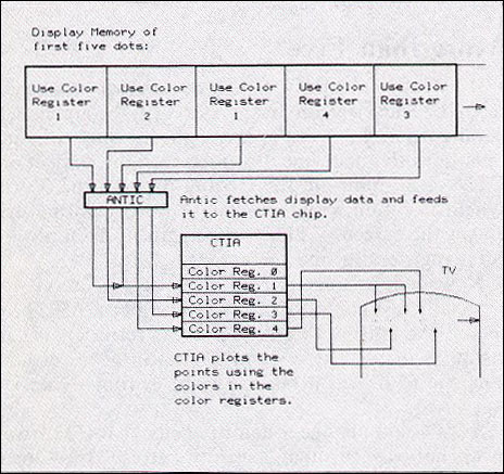
Inside the Atari is stored a copy of what is currently going on the TV screen. This is called "display memory". For a given point on the screen, or a group of points, some way of determining the color to be used when plotting must be stored in this memory. In the Apple the color of the point(s) is stored directly. In the Atari, the color information is stored in a "color register". When in display memory, the color of a point is specified, and a color register number is stored rather than the actual color code.
To plot a red point, one tells the display memory that this point will be plotted in the color and brightness stored in color register 1, then one puts color red at some brightness into that color register (see Figure 15).
There are five available color registers, numbered 0 through 4. Color register 4 is also known as the "background color register". It specifies the color and intensity for any place on the screen where nothing else is written. (In graphics modes 3 to 7, this means the color of the area between any plotted pixels. In mode 0, it means the area around the character display field, the border area, not the color behind characters.)
This approach may seem more complex than necessary, but it has advantages. It saves memory, as only two bits at most are required to specify the color of a pixel in the display memory. It adds flexibility. All we have to do to change the color of every point on the screen using the same color register is modify that register, which can be done with one POKE statement. To turn the entire screen red, then black, ("RED ALERT"), we merely need to POKE statements. In a machine without the Atari's sophistication, massive and slow rewrites of display memory would be required.
Color registers are one byte long. The upper four bits determine the color (0-15), the lower four specify the brightness. Only the top three of the four brightness bits are used, so there are eight levels of brightness, and 16 colors, or 128 total shades of color. Note that in this register, values 0-15 are color #0 in different intensities, 16-31 are color 1, and so on. If we just count this register upwards, we will pass through all 16 colors, each increasing in intensity to the highest level before moving on to the next color. If you will run program 9, you will see the screen counted through all the different shades. The table below lists the different colors.
20 REM ALL POSSIBLE COLORS.
25 POKE 709,14:REM SHADOW REGISTER
30 FOR C=0 TO 255 STEP 2
40 PUKE 710,C:REM SHADOW REGISTER
50 PRINT "COLOR REGISTER=";C
60 FOR DELAY=1 TO 180:NEXT DELAY
70 NEXT C
Program 9.
How Basic Handles Colors
|
|||||
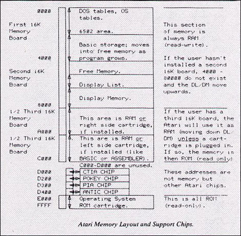
Up in high memory there is some memory which is not read-write, regular old RAM. When one writes or reads from these locations, one is communicating with other chips in the Atari which help support the 6502 (Figure 16). One chip, called CTIA, handles colors and graphics generation. There are five locations ("hardware color register addresses"), which are the five color registers. Now CTIA looks at these registers to find out the color needed whenever it plots a given character or point. During the refresh process of updating the screen, it looks at the registers many times, fetching the colors for displayed data.
The operating system also maintains five "shadow registers". These are normal RAM memory locations. At the beginning of each screen refresh, these five color shadow registers are copied into the corresponding five hardware locations. Basic deals with these shadow registers.
One reason for maintaining these shadows is that the CTIA color register locations are "write only". One cannot read out of those locations where the color was just written in. They are not memory locations; they are chips, which we write to by POKEing simulated memory locations. If we wanted to read a color register and we did not have it stored somewhere (in a shadow register), we could not. Being able to read registers is handy, for example, in rotating a color from one register to the next; you use the shadow registers for this.
Basic's SETCOLOR (color reg #), (col #), (lum #) takes: (16 X color #) + lum and POKEs that value into the shadow register. One sixtieth of a second later, at the beginning of a screen refresh, the operating system copies this value into the CTIA hardware color registers and that chip then begins using it to plot data on the screen. A direct POKE to the operating system shadow locations is equivalent to a setcolor. For example: SETCOLOR 2,4,10 is the same as POKE 710,(4*16)+10.
The designers of Basic also had to come up with some way for the user to specify what color a given point or character should be. For this they have the COLOR (#) statement. It specifies which color register to use when plotting data, and remains in effect until the next COLOR statement.
|
The argument, or number, is not a color register number. The designers of Basic tried to keep the user away from bits and bytes discussions. The COLOR argument at first appears random.
The argument of the COLOR statement is the data that is written into display memory to specify colors. The Atari has 2 and 4 color graphics modes, using 1 or 2 bits to specify color register. For example, COLOR 0 is usually background because a 00 written into display memory plots nothing, therefore forcing the background color to appear there.
Note: SETCOLOR (n), color, lum always sets color register n. The color register number given is equivalent to the SETCOLOR register number.
In character modes (0,1,2) more than 1 or 2 bits are written into display memory. The COLOR argument is actually the character byte written in memory.
Now you understand the five color limit, for there are only five color registers.
More than Five?
A refresh on the TV screen occurs sixty times per second. The electron beam starts at the upper left hand corner, goes all the way right for one scan line, then does the next line down left to right, and so on. CTIA is responsible for feeding data to the TV in synchronization with this scan. For every dot plotted up on the screen, CTIA looks again to its hardware color registers to find the color.
Now while a screen refresh is very fast to us, it is not especially fast compared to the speed of the 6502 processor. We must not think of a screen refresh being an instantaneous event, we must think in terms of how long the 6502 sees it taking, which is roughly an Ice Age or so.
If we could change a color register that CTIA was using halfway through a screen refresh, the screen below that point would reflect CTIA using the new colors. For example, if we were in graphics 7 and modified the background hardware register halfway though a refresh from green to blue, the screen will shift from green to blue in the middle of the TV frame for all those background points (see Figure 17).
Color Registers. |
If we were to put Basic to work changing the color register as fast as it could (i.e. FOR R=0 to 255:POKE 53274,R:NEXT R) we would find that Basic would not be able to get more than one change in each frame. This is because Basic is so slow in execution, and this is why only five colors can be shown at one time if we use Basic. The five colors do not include players and missiles, which can have independent colors.
Basic needs high speed help to assist in getting a demanding job done. We have to use machine language.
Machine Language
Machine language, the human equivalent of which is called assembly language, is an art few people really love. The Atari will execute machine language instructions in times measured in the millionths of a second. Machine code is hard to understand, a pain to debug, and generally has other annoying characteristics, which is why "high level" languages such as Basic were developed in the first place.
We will provide an assembly routine that is easy to load and use from Basic. The routine will handle the demands of the 6502 so you do not have to worry about them. By setting up various tables, again from Basic, in a fairly easy way, you can have as many colors on the screen as you like, all without worrying about assembly, execution speeds, timing, and so on.
Figure 17. |
||||||||
Table of Contents
Previous Section: Notes & Discussion
Next Section: Display List Interrupts