1 Rebuilding Paddles and Joysticks
The easiest way to learn how to build controllers for your home computer
is by rebuilding a commercial paddle or joystick. This is a useful training
exercise and, in many cases, a necessary project because commercial paddles,
which may cost up to $60, are not built very substantially, and they often
don't stand up to the rigorous workouts they get.
Commercial paddles can fail for several reasons: wires
can be broken inside the cables, connectors can be bent or crushed, the potentiometer
wipers can fail to make contact, or the pushbuttons can break mechanically.
Virtually all of these failures are due to the breakage of weak parts that
any competent designer would have realized were inadequate for their intended
use. This chapter will concentrate on teaching you to fix this kind of controller
failure. Fortunately, most of these breakdowns are easily diagnosed and repaired.
Doing so will provide a good lesson in basic electronics.
TYPES OF CONTROLS
We have an Apple II Plus Computer; most of the controls in this book were
designed and tested for that machine. We will attempt, however, to point
out the changes in the designs that are necessary to adapt them for other
computers whenever we have the appropriate information. Most home computers
have similar electronic circuits for their game controls.
Controls come in two general types: digital and analog.
A digital control (like the Atari paddle) consists of a group of pushbuttons.
An analog control, made up of potentiometers that can be adjusted uniformly
over a range, is much more versatile.
Most of the projects in this book will feature analog
controls, but we will throw in a couple of projects for digital controllers
just for good measure. The various digital paddles are almost identical,
but there are two distinct types of analog controls. They differ in the cost
of their components and in their electrical wiring, and we will point out
these differences.
A WIZARD FOUND THESE PADDLES AND RESURRECTED THEM
Strange as it may seem, it is cheaper, and the final product is better, if
you rebuild paddles rather than buy new ones. Let's see what it would take
to reconstruct a beat-up pair of Apple paddles and end up with units that
are better than the originals. Let's assume that there are broken wires in
the cables, that the plug has a missing pin, and that one of the pushbuttons
and both of the potentiometers are broken.
The heart of the paddle is the potentiometer (pot), the
electrical component that is located beneath the knob and controls the adjustment
range. (See the Electronics Tutorial in Chapter 14 for more complete explanations
of the different electronic components used in the projects.) The maximum
resistance of the pot is measured in ohms. The Apple, unfortunately, uses
a paddle pot with a value of 150K ohms (K indicates thousands).
Pots of this value are often hard to locate. Other computer
manufacturers use much more common values, like 100K ohms and 1 meg-ohm,
for their paddle pots. In order to rebuild the paddles you will need to buy
two new pots. (The information in the section on correction capacitors demonstrates
that it is possible, though somewhat complicated, to use lower values for
the paddle pot.)
You can obtain decent pots from mail-order electronics
houses or from local electronics supply stores that sell to the public (look
for ads for the latter in your local Yellow Pages). Radio Shack pots are
of such poor manufacture that we cannot recommend them. Pots advertised as
Mil Spec (built to military specification) are usually excellent, but the
150K value is rare.
A good pot will be completely sealed, will feel very
smooth mechanically, and will be linear, i.e. a graph of how far the knob
is turned versus the resulting change in resistance will be a straight line.
Most good pots will have quarter-inch round stems. If you want to use the
knobs from the Apple paddle, you will have to file the shaft flat on one
side.
The next item on our agenda is the paddle pushbutton,
often referred to as the FIRE button. A good pushbutton should make a click
that can be heard and felt. The button should be about 3/8-inch in diameter
so that using it doesn't tire your finger. A good quality pushbutton switch
will cost up to $3. Many of the better ones are slightly larger than the
factory originals, so you may have to enlarge or move the hole.
Since the index finger can control the FIRE button faster
and more precisely than the thumb, you may want to move the switch to the
back of the paddle where it can be pressed with the index finger when the
paddle is held in either hand.
The cable is also a critical component of the paddle.
The wires can be small, but the cable must be mechanically sound and quite
flexible. This project requires two cables (3-wire, 3-conductor), each about
five feet long. We have found that telephone modular cable with four fine,
multistranded wires is good for building paddles. You can purchase satisfactory
telephone cable from Radio Shack. You can also weave several individual wires
into a cable with a Boy Scout rope-making machine or pull #26 wires inside
aquarium tubing. Both of these procedures have worked for us in various projects.
Replacing the plug is another important part of rebuilding
the paddle. On the Apple, the plug is a standard DIP (Dual Inline Package)
plug. It can easily be made from a device called a header, or component carrier,
at a cost of about $1.25. A header looks something like a standard chip,
but has a row of tiny forks to which the individual wires are soldered. Whenever
you are soldering on this device, plug it into a loose socket so that the
pins will be held straight and will not loosen in the plastic.
MECHANICAL REBUILDING
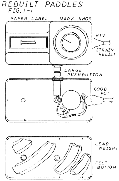
You will note in figure 1-1 that several mechanical changes were made to
the paddle case. First, the new pots were mounted and, if necessary, filed
flat to accept the knob. The new switches were mounted in the original holes;
you can relocate them if you want to. Paper labels clearly identifying the
paddle number were put on the front of the case and covered with transparent
tape. A line was drawn on the knob with a felt-tip marker to indicate the
amount of turn.
To give the paddle a solid feel, weights were glued into
the bottom half of the case. We used lead wheel weights that had fallen off
automobile wheels; they were scavenged on bicycling trips. Fishing weights
would also serve the purpose. Such weights can be installed with either epoxy
or silicone sealant. We covered the bottom of the paddle with felt, attaching
it with rubber cement, to further improve the feel and insure that the paddle
will not scratch furniture. In addition, it may be necessary to enlarge the
notch for the cable, particularly if you use telephone cable.
ELECTRICAL WIRING
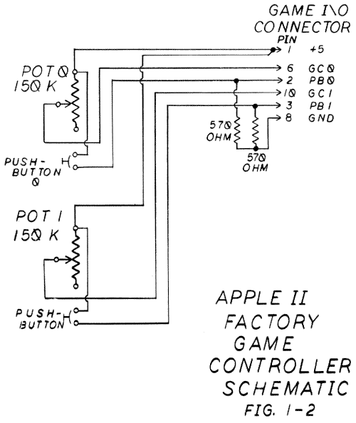
Figure 1-2 shows the standard schematic for an Apple paddle. You may want
to refer to page 100 of the Apple II Reference Manual for more details. Note
that two resistors from the original paddle, with a value of 570 ohms each,
are mounted in the game connector. You may use resistors of any value from
570 to 1000 ohms, rated at 1/4 watt and 5% tolerance.
You should do the soldering with a small pencil-type
iron of from 25 to 42 watts and resin-core soldering. The use of acid-core
solder on electronic equipment will destroy it forever and always-no resurrection
is possible.
CHECK AND DOUBLE CHECK
The professional procedure for making up a circuit from the schematic requires
two photocopies of the schematic drawing and a colored pencil. As you solder
the connection, neatly color in each connector and wire on the first copy
of the schematic. When everything is colored in, you are finished.
The second copy is used for the test. When your work
is complete, take the fresh copy of the drawing and, with a multimeter, carefully
check each line for continuity, coloring it in on the drawing. You will often
find that you have missed soldering a wire or two in the circuit.
SOLDERING
You may want to unbolt the potentiometer and the pushbutton to make soldering
easier. Cut the cables to length and very carefully strip back the outer
insulation. Be especially careful not to nick the wires. A small pair of
wire strippers, the type that look like pliers and have an adjustment bolt,
are best for this job.
If you use telephone modular cable, you will find that
you have four wires, one more than is necessary. The best use for this extra
wire is to double up and use two wires for the line from pin 1 (the +5 volt
power supply), which goes to one side of the pot and one side of the switch.
This will reduce the chance of the pushbutton affecting the pot reading.
You will note that figure 1-1 also shows a jumper between
the unused leg of the pot and the center terminal. This is considered good
electronic practice and helps performance somewhat when the pot begins to
wear. If the pushbutton has three terminals, be sure to use the pair marked
C (common) and N.O. (normally open).
To attach the header, strip back the insulation from
the cable and expose the wires, trim them neatly to the length required,
and tin about 1/8-inch of bare wire on each with solder. Plug the header
into an empty socket and locate the mark for pin 1. The cables usually are
fed in from the pin 8 end to make them easy to plug into the Apple. Now you
can fit the wires into the tiny forks, holding them with a pair of long-nose
pliers, and solder them in place.
Clip off the excess wire with a small pair of diagonal
cutters. Place the two pull-down resistors into the header, shortening and
bending their leads to fit the forks precisely. Hold the wires with long-nose
pliers, not your fingers, while you are soldering.
If you have a multimeter, you can now check out your
work without the risk of plugging it into the computer. Put it on a low ohms
scale and measure for continuity between the pins on the connector and the
appropriate points indicated in figure 1-2. In addition, measure from pin
l, the +5 supply, to pin 8, the ground, to insure that impedance is greater
than 50 ohms, and that it remains greater than 50 ohms for all settings of
the pot and all pushbutton combinations. It is a good idea to have a friend
check your work for you. In any case, checking it three times usually insures
correctness.
THE SMOKE TEST
Turn off your computer. Never attach or remove anything from a computer with
the power on. Check again for your #1 pin, properly plug it into the paddle
connector, and turn the computer back on. If the computer behaves irregularly,
turn it off immediately, unplug the paddle, and recheck all your work. An
example of irregular behavior: if the disk routine starts up over and over
again, it indicates a short to the +5 pin.
If nothing untoward happens, you can run the Controller
Checkout program in chapter 15 to check out the functions of the paddle and
pushbuttons. If all is well, turn off your computer and remove the paddle
connector.
FINISHING UP THE JOB
Your next task is to install the bottoms on the paddles and build up a strain
relief for the cables out of silicone sealant. This material, used for bathroom
caulking, is available at most hardware stores. The clear sealant is best
for electronics work since it is the least messy. (This material is quite
irritating if it gets on your skin or in your eyes, so be careful using it.)
You may have to apply two coats of sealant to get a neat result. Allow each
coat to dry overnight.
A FINAL TOUCH
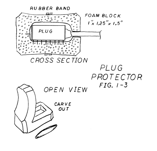
One of the most common problems with Apple paddles is bent pins in the connector.
This isn't a failure in the design; computer users simply leave them lying
around unprotected. Figure 1-3 shows a protective foam block for the connector
that should be used whenever the paddle isn't attached to the computer. The
best material for this is the stiff but flexible white foam that is used
to pack delicate electronic equipment. This foam is easily worked with a
pair of scissors. A rubber band holds the foam block in place. A loose socket
can also be used to protect the pins.
JOYSTICKS
Most of the procedures we use in reconstructing a paddle can also be used
for fixing a joystick. You can obviously replace the connector and the cable.
In this case, the cable will require more conductors: four conductors if
there is one pushbutton, five if there are two, and six if correction capacitors
are required. A double run of the modular telephone cable with stranded wires
works much better than the commonly used ribbon cable. There is usually plenty
of room in the joystick case to install new pushbuttons; it is just a matter
of matching holes.
The joystick element containing the two pots and the
mechanical linkage is more difficult to replace. It is almost impossible
to find replacements for just the pots, and the commonly available replacements
for the entire element are not very good. You may also have to use pot values
other than those originally intended and add correction caps (see the explanation
of correction caps below). Joystick elements with centering springs and tabs
are usually better made than those without.
One of the special problems that occurs with joysticks
is failure to zero. When this occurs, a pot will read a small positive number-instead
of zero-even though the pot is in its extreme low position. Failure to zero
is usually caused by poor mechanical construction of the joystick element.
There is a procedure to correct this problem, described in the section on
Zeroing Joystick Elements below, but it is difficult to complete successfully.
Be sure to provide proper strain relief for the cable
where it exits from the box. The wires of ribbon cables often break at this
point.
CORRECTION CAPACITORS
One of the most common ways in which home computers read input from paddles
uses a timer circuit. You can tell if this is the procedure used by your
computer by counting the wires from the paddle pot back to the computer.
If there are two wires (the +5 and pot wires), then the pot is wired as a
variable resistor and is used in a timer. If there are three wires (the +5,
ground, and pot wires), then the pot is used as a variable voltage device,
or true potentiometer. The Apple, the Commodore VIC-20, and many other computers
use the timing circuit. Some Radio Shack models use true potentiometers.
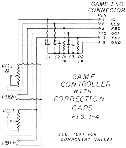
The timing circuit can be adjusted for pot values lower
than the original values. This adjustment can be made by adding small capacitors
within the paddle and thus requires no modification of the host computer.
Figure 1-4 shows how the correction caps can be added to a standard controller
circuit.
The Correction Cap Calculation program in chapter 15
will assist you in calculating the correction cap values for the Apple II.
The program works by taking the maximum value of the pot and multipying it
by the value of a small cap inside the computer to form a constant. You then
divide that constant by the new maximum pot value and subtract the original
cap value. This gives you the correction cap value required.
For the Apple the original maximum pot value is 150K
ohms. The original cap is a .022 microfarad. If you have a different computer
you can probably get the maximum pot value by opening a paddle and either
reading the value off the pot or measuring it with a multimeter. You can
usually find the cap on your computer's schematic by tracing the wires from
the paddle port back into the machine. These values can then be placed in
line 18 of the program.
The correction caps are soldered from the game control
pin to the ground. If they are put inside the paddle, you must bring a ground
wire out to the paddle. Alternatively, they can be mounted on a small printed
circuit board a few inches down the cable from the connector and encased
in packing foam.
It is difficult to obtain the exact values desired, so
you are probably just as well off to buy an inexpensive selection of caps
and use trial and error.
To test your work, run the Controller Checkout program
again. If the reading reaches 255 before the pot is turned to its maximum,
the cap is too big. If the reading never reaches 255, the correction cap
is too small. Several small caps in parallel may be needed to get the correct
value. The Correction Cap Calculation program contains the limitations of
this procedure.
ZEROING JOYSTICK ELEMENTS
A common failure of joysticks, particularly cheap ones, is not to go to zero.
This can be corrected, but the procedure is tricky, and it is possible to
ruin the joystick element. If you decide to attempt the correction, first
unsolder and disassemble the joystick element and remove the potentiometer.
The metal back must then be removed from the pot by straightening the small
metal tabs. Do it carefully, because these tabs will not bend many times
before they break. In removing the back be careful not to lose any of the
internal parts.
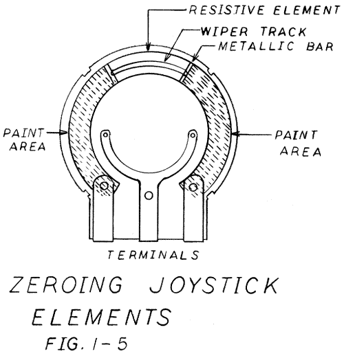
Now the pot element should look like figure 1-5. Note
that there is a small active area of resistive element in the middle and
two large inactive areas on either side. The problem is that the inactive
areas have too much resistance to read as zero. Look closely at the limits
of the wiper track, which leaves a mark, in the active area.
The trick is to reduce the resistance of the inactive
areas. This can be done by painting over them with sterling silver pigmented
paint, available at electronics stores, or with a homemade paint made from
clear nail polish and lock graphite. Needless to say, the expensive silver
paint is better.
Carefully wipe clean the inactive areas. Make up a mixture
of nail polish and graphite into a paste on a smooth surface, then paint
the inactive area of the pot element, covering the terminal end and continuing
until you just touch the end of the wiper track. Be very careful that the
paint goes nowhere else, particularly not where it might touch the metal
case or the metal feelers for the central terminal. It may take two coats
for complete coverage. Allow the paint to dry thoroughly.
Now reassemble the pot and the joystick element. Resolder
the wires according to the schematic. Run the checkout program. If correction
caps were used you may have to adjust their values.
| Parts List Rebuilding Game Paddles and Joysticks |
||||||||||||||||||||||||||||||||||||
|
||||||||||||||||||||||||||||||||||||
|
Return to Table of Contents | Previous Chapter | Next Chapter