A light pen is a fascinating input device. By pointing a light pen at the computer's screen and pressing its input button, you can make selections from a menu, draw a picture, or perform whatever function the computer program you're using allows. The biggest attraction of a program which uses a light pen is that you don't have to use the keyboard-using a program becomes as simple as pointing.
To understand how a light pen works, you must know a bit about how your computer's monitor displays a picture. Pictures on the screen are made up of tiny dots of light. These dots are produced from an electron gun in the monitor which shoots electrons at the screen. These electrons excite the phosphor coating on the screen, causing it to emit light. In this way, the electron gun actually "paints" the picture, dot by dot, row by row, until the screen is filled. All of this is done in a fraction of a second and is updated many times every second.
Your computer keeps track of where the beam of electrons from the electron gun is at all times. The light pen, when pointed to a spot on the screen, triggers the computer to store the location of the beam as it passes. These x and y coordinates are placed in special registers of your computer. Since the position of the beam stored is the same as that of the light pen, programs can determine where you're pointing the light pen by checking the values contained in these registers. The program can then use this information to perform various functions, like drawing a line or selecting an option.
Here's what you'll need to make a simple light pen:
| Quantity |
Part |
Part Number |
| 1 |
Solderless breadboard |
276-175 |
| 1 |
7400 quad 2-input NAND gate IC |
276-1801 |
| 1 |
TIL infrared phototransistor |
276-145 |
| 1 |
1K ohm resistor (Commodore only) |
271-8023 |
| 1 |
9-pin D-subminiature female |
276-1538 |
| 1 |
Push button microswitch (normally open) |
275-016 |
| You'll also need some stranded
copper wire, a ballpoint pen, and some solid copper wire. |
||
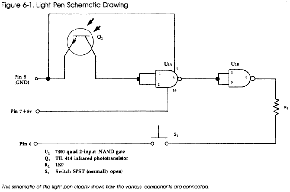
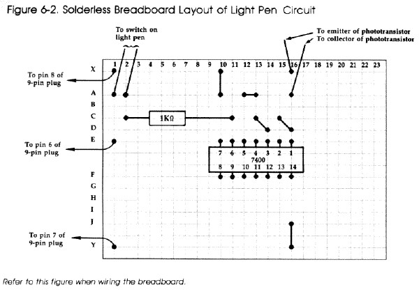
When building the light pen, refer to Figure 6-1,
the schematic drawing for the light pen circuit, and Figure 6-2, the solderless
breadboard layout, as you follow these instructions:
|
1. Solder lengths of solid copper wire to
pins 6, 7, and 8 of the 9-pin plug. These wires will connect the plug with
the solderless breadboard. 2. Insert the wire from pin 6 to point E1 of the breadboard, the wire from pin 7 to point Y1, and the wire from pin 8 to point X1. 3. Insert the 7400 IC in the breadboard so that its pin 1 is at point E16 and its pin 8 at point F10. You can tell which pin of the IC is pin 1 by one of two methods: Pin 1 may have a circle indented in the plastic beside it. Alternatively, there may be a semicircular indention at the end of the IC where pin 1 is located. In this case, pin 1 is the first pin in a counterclockwise direction from this indention (looking at the top of the IC). In either case, the remaining pins are numbered counterclockwise around the IC. 4. Insert five solid copper jumper wires as follows:
5. Remove the ink cartridge from the ballpoint pen. The barrel of the pen will act as the body of your light pen. With your hot soldering iron, carefully melt a small hole at the end of the barrel where the ballpoint used to be for the wires. |
||||||||||||||||||

|
Warning: Be sure to clean off the tip of your
soldering iron when you're finished. If you intend to use your soldering
iron for serious work, it's a good idea to change the tip of your iron
after using it to melt plastic. Substances from the burning plastic will
adhere to the tip of your iron, making it unsuitable for serious soldering
work. [We found that it wasn't necessary to burn a hole for installing the
TIL 414 phototransistor when we used a BIC ballpoint pen-Editor.] |
||||||||||||||||||
|
|
6. Cut four pieces of stranded copper wire
about 30 inches long to connect your light pen with the solderless breadboard.
These wires must be long enough to allow you to move the light pen freely. 7. Solder one of the four wires to the emitter lead of the phototransistor. Another wire should be soldered to its collector lead. Attach a small piece of electrical insulation tape around both the collector and emitter leads so that they won't come in contact and short out. 8. Pull the wires of the phototransistor through the pen barrel and glue the phototransistor in place at the "tip" end. Be careful not to get any glue over the phototransistor's light-sensitive part. 9. The wire from the emitter plugs into position X16 of the solderless breadboard, while the wire from the collector inserts into point A16. 10. Solder the remaining two 30-inch wires to the leads of the microswitch. Pull the wires through the hole you melted and out the open end of the pens barrel. Glue the microswitch to the barrel of the pen. 11. One of the wires from the switch inserts into point A1 on the breadboard, while the other goes into point A2. 12. Insert the 1K resistor between points C2 and C11 of the solderless breadboard. (For the Atari version of this circuit, use a jumper wire in place of the resistor.) |
||||||||||||||||||

|
To check that your light pen is operating
properly, turn off your computer and insert the 9-pin plug into control
port 1 of the Commodore 64/128 and Atari computers. (The VIC has but one
control port.) A light pen won't work in control port 2 of the Commodore
64 and 128 computers. Turn on your computer, type in, and run the appropriate
version of Program 6-1. Program 6-1-Commodore 64/128 5 A = 53267:B = 53268 10 PRINT "X=";PEEK(A),”Y=";PEEK(B) 20 GOTO 10 Program 6-1-VIC-20 5 A=36870:B=36871 10 PRINT "X=";PEEK(A),"Y=";PEEK(B) 20 GOTO 10 Program 6-1-Atari 5 A=564:B=565 10 PRINT "X=";PEEK(A);'Y=";PEEK(B) 20 GOTO 10
Download (Saved BASIC)
Move your light pen around the screen while pressing the microswitch.
The numbers of the two columns should change, giving you the coordinates
of the point of your light pen. |
||||||||||||||||||
|
|
Warning: You may have to adjust the brightness
of your monitor to get your light pen to work properly. |
How It Works
Your computer is set up to store the position of the electron beam every time pin 6 of the control port, normally at a logic high state, is set low. The light pen circuit is designed to set this pin low. This triggers the computer to save the electron beam's position when it passes the light pen.
The phototransistor acts as a very fast switch. Normally, the path between the emitter and collector of the phototransistor is like that of an open switch. The moment the beam of the electron gun passes the point at which the phototransistor is aimed, enough light is emitted to turn the transistor on. When this happens, the connection between the emitter and the collector of this device is effectively that of a closed switch. Since the emitter is connected to ground, the inputs of the NAND gate, which are attached to the collector, are grounded as well.
The operation of NAND gates and other logic building blocks is explained in greater detail in Chapter 10, "Digital Logic." Let it suffice to say here that the two NAND gates used in the light pen circuit act as a noninverting buffer. Noninverting buffers are used when a signal isn't sufficient to drive the inputs of other IC gates. The output of this type of buffer is the same as its input.
The output of the buffer is connected to pin 6 of the control port through a resistor and the push button switch. When the push button switch is open, the light pen circuit is disconnected from pin 6 of the control port. The push button switch must thus be pressed if this pin is to be triggered.
When the light pen is aimed at a point on the screen and the button is pressed, several things happen. Because the screen picture is refreshed many times each second, the electron beam passes the phototransistor at least once in the time it takes to press and release the button. Before and after the beam passes the phototransistor, the input and output of the buffer are logic high, and as a result, pin 6 remains at that state. The moment the beam passes the phototransitor, the input and output of the NAND gate buffer are set low. Thus, pin 6 of the control port is set low for a fraction of a second, long enough to trigger the computer to store the location of the electron beam.
Programming with
the Light Pen
As you ran the test program, you probably noticed that when the pen
was held at one spot, the coordinate numbers didn't remain constant, but
instead stayed within a relatively small range. This must be taken into
account when writing programs to work with your light pen.
Another point to remember is that once you use the
light pen, the values remain the same in their registers until the light
pen is used again. This means your program should have a way of checking
that the values in the register are a new selection rather than a previous
selection. For instance, suppose the registers contain the values 120
and 125 from a previous menu selection. When you put up your next menu,
you expect the user to make another selection with the light pen. In order
to determine where the light pen is pointed, you might compare the register
values to a specified coordinate range. If the range includes one of the
values from the previous selection, the program would immediately proceed
as if the pen is pointed in this range before the user even has a chance
to use the light pen.
One way to avoid this problem is to check whether
the user has pressed the push button again. This insures that the previous
values in the register have no effect on the selection. Since the light
pen line (pin 6) is the same as that of the fire button, you can check for
it the same way you would check for the fire button. Another way to avoid
this problem is to make sure two consecutive menus have no ranges in common.
|
|
Try entering and running the appropriate version
of Progam 6-2, which shows how a light pen can be used to make selections
from a menu. When the menu appears, just point to the asterisk (*) beside
your choice and press the microswitch. The screen clears and the choice you
made appears. After a short delay, the word CONTINUE is displayed with an
asterisk in front of it. Point your light pen to the asterisk and press the
microswitch to return to the menu. Program 6-2-Commodore 64/128 QK 100 REM * LIGHT PEN DEMO * HA 150 A$=CHR$(147):PRINTA$ BB 160 PRINTTAB(10)"THREE CHOICES" MQ 170 PRINT:PRINT GJ 180 PRINTTAB(5)"* CHOICE ONE" GF 190 PRINT:PRINT:PRINT:PRINT DA 200 PRINTTAB(5)"* CHOICE TWO" RC 210 PRINT:PRINT:PRINT:PRINT FK 220 PRINTTAB(5)"* CHOICE THREE" DD 230 A=PEEK(53267):B=PEEK(53268) FJ 240 IF A>55 THEN 230 EB 250 IF (B>70) AND (B<80) THEN 300 HG 260 IF (B>110) AND (B<120) THEN 330 XP 270 IF (B>150) AND (B<160) THEN 360 HF 290 GOT0230 RF 300 PRINTA$ DA 310 PRINT"CHOICE ONE" BF 320 GOTO 400 KH 330 PRINTA$ GD 340 PRINT"CHOICE TWO" RJ 350 GOTO 400 FK 360 PRINTA$ QS 370 PRINT"CHOICE THREE" KS 400 FOR I=0 TO 1500 XP 410 NEXT I:PRINT CB 420 PRINT"* CONTINUE" AS 430 IF PEEK(53267)<55 AND PEEK(53268) <70{2 SPACES}THEN 150 KX 440 GOTO 430 Program 6-2-VIC-20 XF 10 A$=CHR$(147) :PRINTA$ JK 20 PRINTTAB(4)"THREE CHOICES" CE 30 PRINT:PRINT BQ 40 PRINTTAB(5)"* CHOICE ONE" CF 50 PRINT:PRINT:PRINT:PRINT HF 60 PRINTTAB(5)"* CHOICE TWO" JC 70 PRINT:PRINT:PRINT:PRINT FG 80 PRINTTAB(5)"* CHOICE THREE" RH 90 A=PEEK(36870):B=PEEK(36871) CA 100 IF A>65 OR A<40 THEN90 QQ 110 IF (B>30) AND (B<40) THEN150 DH 120 IF (B>50) AND (B<60) THEN180 HJ 130 IF (B>70) AND (B<80) THEN210 SX 140 GOT090 MQ 150 PRINTA$ CK 160 PRINT"CHOICE ONE" BR 170 GOT0230 GS 180 PRINTA$ HP 190 PRINT"CHOICE TWO" AS 200 GOT0230 HX 210 PRINTA$ XE 220 PRINT"CHOICE THREE" DF 230 FOR I=0 TO 1500 GS 240 NEXT I:PRINT DP 250 PRINT"* CONTINUE" QD 260 IF PEEK(36870)<40 AND PEEK(36871) <40{2 SPACES}THEN10 CF 270 GOT0260 Program 6-2-Atari PF 100 REM LIGHT PEN DEMO AN 150 PRINT CHR$(125) NO 160 PRINT "THREE CHOICES" LD 170 PRINT :PRINT :PRINT CB 180 PRINT "* CHOICE ONE" LF 190 PRINT :PRINT :PRINT DC 200 PRINT "* CHOICE TWO" KO 210 PRINT :PRINT :PRINT LC 220 PRINT "* CHOICE THREE" PH 230 A=PEEK(564):B=PEEK(565) NB 240 IF A>90 THEN 230 CK 250 IF (B>25) AND (B<35) THEN 300 DC 260 IF (B>45) AND (B<55) THEN 330 DA 270 IF (B>60) AND (B<70) THEN 360 GJ 290 GOTO 230 AK 300 PRINT CHR$(125) PC 310 PRINT "CHOICE ONE" GC 320 GOTO 400 AN 330 PRINT CHR$(125) AN 340 PRINT "CHOICE TWO" GF 350 GOTO 400 BA 360 PRINT CHR$(125) IO 370 PRINT "CHOICE THREE" ME 400 FOR I=1 TO 15:PRINT :NEXT I CC 410 PRINT P6 420 PRINT "* CONTINUE" DE 430 IF PEEK(564)<90 AND PEEK(565) >80 THEN 150 GI 440 GOTO 430
Download (Saved BASIC)
|
Return to Table of Contents | Previous Chapter | Next Chapter