Display List Interrupts
The Atari computers really have two processors. One is called ANTIC and the other is the regular 6502. ANTIC has its own special language and is devoted to display work. ANTIC works with "display blocks". A display block is a group of horizontal scan lines, all in the same display mode. Think of it as a long thin horizontal bar, 8 scan lines high in graphics 0, 16 scan lines in graphics 2, and 1 scan line in graphics 8. The height is determined by the size of plotted data in the particular mode. Atari displays are composed of stacked display blocks. There are 24 stacked blocks in graphics 0, which means 24 lines of text, and 96 stacked blocks in graphics 7.
Previous sections have shown how to modify the program ANTIC uses, called a "display list", to achieve mixed graphics modes and other effects, such as scrolling. There is one change to the display list we have not yet covered, because of its complexity and the requirement of using assembly language. The remaining topic is the display list interrupt. In assembly language, a display list interrupt is given the label DLI.
A display list interrupt is established by setting the top bit of a display list instruction. (To Basic programmers, this means to add 128 to the instruction.) For example, a graphics 0 instruction with a DLI added is (2 + 128), or 130. Any display list instruction can have an interrupt added.
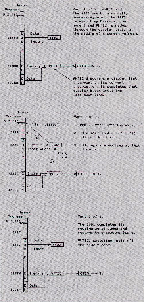
ANTIC finds the top bit of the instruction set (128 added). It goes ahead and completes the current instruction or display block until the last scan line. At the beginning of the last scan line, ANTIC turns and tells the 6502 to process the request immediately.
The 6502 looks at locations 512 and 513 in memory. In these it finds 16 bits of address (stored in low byte, high byte format, for you advanced coders). The 6502 jumps to that address. A POKE to an ANTIC location is required to enable this sort of interrupt before the 6502 will be bothered.
At the location whose address we put in 512 and 513 we must have an assembly language routine waiting to "service the interrupt", or make the 6502 do whatever it is we want the computer to do. At the end of this routine, we send the 6502 back to its original task with an RTI (return from interrupt) instruction (see Figure 18).
This is probably a new concept to Basic programmers. The best Basic analogy is the TRAP statement. TRAP specifies a line number to go to if there is an error, just as 512 and 513 specify where to go if there is an interrupt. Presumably, at that line number you have written a routine to handle errors. This is the equivalent of the interrupt service routine. You never know where an error might happen when you are executing your Basic code, just as you never know when an interrupt will occur.
The development of an assembly language routine that will be as flexible and easy to use as possible, yet run on any memory size Atari, is quite a task.
|
Details, Details
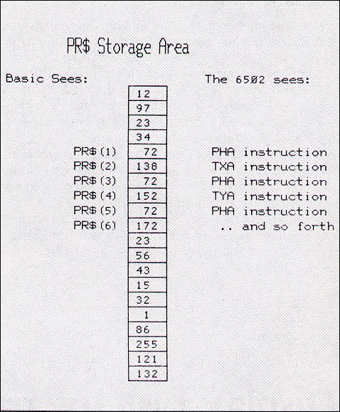
The assembly routines must be able to fit anywhere in memory, since the memory size on different computers varies, as does program size. We've placed the entire routine into a string (PR$), and we will let the Atari decide where to put it.
A string is a collection of characters, frequently letters, numbers, and punctuation. Inside the machine all those characters are stored as bytes of memory, one per character. An assembly routine is also a collection of bytes. Since the Atari stores a string as a group of bytes, one at a time, in memory, we could make the string's characters (bytes) be the same as our assembly routine, and store the program in the string (see Figure 19).
|
The Basic sub-routine to be provided reads the bytes of the assembly program into the string, one at a time. The CHR$ function takes the contents of the argument and directly stores it into the string, which is just what we want since we do not care about the actual characters. After the routine sets up the string, it links our table of colors to the program, enables display list interrupts, and returns.
The method for specifying colors is to build a table of them, five at a time (for the 5 color registers). Each time there is a display list interrupt, starting at the top of the table, the next five colors are copied into the hardware registers by the service program (in PR$). The idea is that the first display list interrupt causes the first five bytes of the table to be copied into the hardware registers, causing the colors of CTIA to change at that point. The next display list interrupt causes the second group of five color bytes to be copied into the hardware registers, again changing the colors, further down the screen. By setting interrupts and modifying the display list from Basic, you can change colors any time you like from one display block to the next. This lets you get as many colors on the screen as you want, oriented towards display blocks (see Figure 20).
|
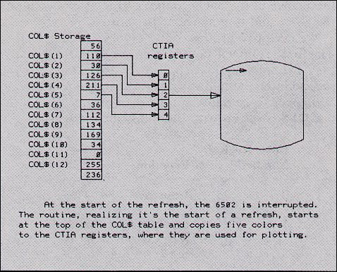
How shall we set up the table? Let's use another string, COL$. The first five bytes (characters) of the string will correspond to the first display list interrupt colors, the next five bytes for the next five, and so on. Since the routine can handle a maximum of 255 bytes, this means we have a total of 255/5=51 interrupts, which is plenty.
The next problem is how the assembly routine determines when we are at the top of the screen, in order to know when to start over at the top of the table in the string. This is done by setting an interrupt at the very first display list instruction on the screen, which is a 112 (8 black scan lines). There is a hardware register called VCOUNT which tells us which scan line we are on, from the top of the screen. We read it, and if it corresponds to the blanking line at screen top, we know to start at the beginning of the table again. The routine requires this interrupt to be set. If it is not, random colors will be generated as the 6502 sails past the end of COL$, using any data in memory to determine color and luminance.
The Basic subroutine is called after you set up COL$, which is the table of colors. It requires that the location of COL$ be fixed in memory before it tells the assembly program the location of the color table. After the subroutine is executed control returns to the Basic program that called it (see Program listing 10).
Place your interrupts where you need a color register change, make sure you have the colors ready in the table (COL$), and the assembly routine will do the rest. The moment the display list is modified, the process of copying the new color codes into the hardware registers begins and the colors will change on the screen.
Basic keeps "operating system shadow registers" of the colors in the five hardware registers. When we do a SETCOLOR, we change these operating system registers. At the start of each TV refresh, sixty times a second, these shadow registers are copied by the operating system into the hardware registers. Here the colors stay, unchanged, for CTIA to use, unless something like our special assembly language routine changes them.
The routine requires the "blank 8 lines" instruction executed at the top of the frame to have an interrupt. ANTIC creates that display block, generating blank lines, and on the last scan line of the block interrupts the 6502. The 6502 looks at COL$, pulls out five bytes from the beginning of the table (since this is the top of the screen), and copies those bytes as color numbers into the hardware registers. At that point the colors generated by CTIA change to the new values just entered.
10000 REM **************************
10010 REM
10020 REM * DLI DRIVER / DAVE SMALL
10030 REM * YOU MUST DIM AND FILL
10040 REM * COL$ PRIOR TO GOSUB HERE
10050 REM
10060 DIM PR$(50)
10080 REM
10090 REM * READ PROGRAM INTO PR$
10100 REM
10110 READ X
10120 IF X=255 THEN 10300
10130 PR$(LEN(PR$)+1)=CHR$(X)
10140 GOTO 10110
10150 REM
10160 REM * PROGRAM AS BYTES
10170 REM
10180 DATA 72,138,72,152,72
10190 DATA 162,0,173,11,212,201,07,240,3
10200 DATA 174,01,02
10210 DATA 160,0
10220 DATA 189,03,04
10230 DATA 153,22,208
10240 DATA 232,200,192,5,208,244
10250 DATA 142,05,06
10260 DATA 104,168,104,170,104,64
10270 DATA 00,01,02,03,04,05
10280 DATA 255
10290 REM
10300 REM * LINK COL$ TO PR$
10310 REM
10320 P=ADR(PR$)
10330 PHI=INT(P/256)
10340 PLO=(P-PHI*256)
10350 REM
10360 C=ADR(COL$)
10370 CHI=INT(C/256)
10380 CLO=(C-CHI*256)
10390 REM
10400 REM * FORE IN COL$ ADDRESS
10410 REM
10420 PR$(21,21)=CHR$(CLO):REM LOWCOL
10430 PR$(22,22)=CHR$(CHI):REM HI COL
10440 REM
10450 REM * POKE IN PROGRAM LOAD ADDR
10460 REM
10470 PXHI=INT((P+41)/256)
10480 PXLO=(P+41)-(PXHI*256)
10490 PR$(16,16)=CHR$(PXLO):REM XLO
10500 PR$(17,17)=CHR$(PXHI):REM XHI
10510 PR$(33,33)=CHR$(PXLO):REM XLO
10520 PR$(34,34)=CHR$(PXHI):REM XHI
10530 REM
10540 REM * POKE IN INTERRUPT ADDRESS
10550 REM
10560 POKE 512,PLO
10570 POKE 513,PHI
10580 REM
10590 REM * ENABLE INTERRUPTS (ANTIC)
10600 REM
10610 POKE 54286,128+64
10620 REM
10630 REM * ALL SET! RETURN,
10640 REM
10650 RETURN
10660 REM ******************
Program 10.
PHA
TXA
PHA
TYA
PHA
LDX #0

LDA $040B

CMP #7

BEQ SKIP

LDX $0102


SKIP LDY #0

LOOP LDA $0304,X


STA	$D016,y


INX
INY
CPY #5

BNE LOOP

STX $0506


PLA
TAY
PLA
PLA
RTI
(SCR1)
(SCR2)
(SCR3)
(SCR4)
(SCR5)
(SCR6)
(END)
Program 10A. Assembler routine for
display list interrupts from Program
10.
These color values will stay on the screen until the next refresh unless we place another display list interrupt somewhere, and have five more colors ready in COL$. If we do, at the end of the display block in which the interrupt is set the color register will again change. At each refresh (every sixtieth of a second) the operating system shadow registers will once again be copied into the hardware registers, just to be replaced by our colors again, and this cycle will continue as long as the DLI instructions are in the display list.
We have to determine where on the screen we want a color change, what color registers to change, (the color registers are used differently in various graphics Modes), and then insert in the right values to make a multi-colored screen.
Our example is in graphics 0, the character mode. It will plot the top section of the screen in one color, the bottom in another.
Graphics 0 uses the five color registers as follows. Color registers 0 and 3 are unused. Register 1 determines the luminance of the characters, with same color as register 2. Register 2 contains the color and luminance of the background, and register 4 contains the color and luminance of the border.
We need two groups of five colors stored in COL$. The first group will cover the colors from the first display list interrupt, at the top of the screen, to the second interrupt midway down the screen. The second will cover from midscreen to the bottom.
COL$ is set up with the following colors:| Color Register Number | Function |
| 0 | Unused. |
| 1 | Luminance of charac- ters. Color is same as reg 2. |
| 2 | Color and lum of backgnd behind characters. Not border. |
| 3 | Unused. |
| 4 | Border color and lum. |
*Group 1* |
|
| Col reg 0, unused | COL$(1)=CHR$(0) |
| Luminance of characters = 10 | COL$(2)=CHR$(10) |
| Backgnd color-lum of green, which is color #12, intensity 6. |
COL$(3)=CHR$(12*16)+6 |
| Col reg 3. unused | COL$(4)=CHR$(0) |
| Border Color reg, orange at 6 Orange = color 2. |
COL$(5)=CHR$(2*16)+6 |
*Group 2* |
|
| Col reg 0, unused | COL$(6)=CHR$(0) |
| Col reg 1, lum = 10 | COL$(7)=CHR$(10) |
| Col reg 2, red at 6 | COL$(8)=CHR$((3*16)+6) |
| Col reg 3, unused | COL$(9)=CHR$(0) |
| Col reg 4, border, blue at 6 | COL$(10)=CHR$((7*16)+6) |
Our colors are now set up. We call the routine with GOSUB 10000. It returns control to Basic. We must now set our interrupts in the display list.
A graphics 0 display list is shown on the next page to help us visualize what we will be modifying.
We POKE (112 + 128) into START + 0, to set our first interrupt (as soon as that POKE is executed, the Atari's colors will all change to the values in the first five bytes, and another interrupt midway down the graphics 0 instruction at START + 6 + 15: POKE 2 + 128).
START=PFEK(560)+256*PEEK(561) START +0 +1 +2 +3 +4 +5 +6 +7 .. +29 112 112 112 66 data byte data byte 2 2 2 (blank 8 lines) interrupt here required (2, a graphics 0 instruction, + 64=lms graphics 0 instructions last graphics 0 instruction (halt until next refresh). Sample Graphics Display ListOn the screen will be the colors specified, changing at the interrupt points to the new colors in COL$.
Push BREAK to halt the program. The screen stays changed! This is because the program and color strings are still in the same locations and no one told ANTIC to stop the interrupts. However, as soon as the strings get shifted or destroyed, perhaps during editing, the computer will not have an interrupt service routine anymore, and it will quietly die. (Use RESET to avoid this.) The way to exit the multicolor mode is to remove the interrupts from the display list.
For the next demonstration we will escalate things and put 16 colors on the screen at once in graphics 0. We will make each of the first 16 graphics 0 display blocks a different color.
We will need 16 interrupts; the one at the top of the screen (112), the one at the first true graphics 0 instruction, which is the 66 (666=4+2 -- the 64 tells ANTIC that a display memory address follows, while the 2 is the graphics 2 instruction), and 14 more in the graphics 0 (2) instructions.
110 REM * 16 COLORS AT THE SAME TIME.
120 DIM COL$(255)
130 REM * INITIALIZE COL$ IN GROUPS
140 N=4
150 FOR C=1 TO 80 STEP 5
160 COL$(C)=CHR$(0):REM UNUSED
170 COL$(C+1)=CHR$(0):REM LUM
180 COL$(C+2)=CHR$(N):REM COLOR
190 COL$(C+3)=CHR$(0)
200 COL$(C+4)=CHR$(2):REM GREY BORDER
205 N=N+16
210 NEXT C
220 REM
230 REM * NOW CALL DLI HANDLER
240 REM
250 GOSUB 10000
260 REM
270 REM * NOW DO DL WORK
280 START=PEEK(560)+256*PEEK(561)
290 POKE START,112+128
295 POKE START+3,2+64+128
300 REM
310 REM * NOW POKE IN 14 MORE(GR/0)
320 REM
330 FOR D=START+6 TO START+6+14
340 POKE D,2+128
350 NEXT D
360 REM
370 REM PROGRAM IS NOW RUNNING.
380 REM
500 STOP
Program 11.
COL$ will have a length of 80 bytes, 16 interrupts multiplied by 5 colors or 80 long.
Instead of 80 sets of basic instructions, (COL$=CHR$...) we will use a short loop. Remember that adding 16 changes to the next color (see Program 11).
N=6 (grey color, 6 intensity)
FOR C=1 to 75 STEP 5
COL$(C)=CHR$(0) (colreg 0..unused)
COL$(C+1)=CHR$(0) (character illumination)
COL$(C+2)=CHRS(N) (color, shifts 16 each loop)
COL(C+3)=CHR$(0) (unused)
COL(C+4)=CHR$(2) (black border)
N=N+16 (bump up one color)
NEXT C
This loads COL$ with our desired 15 color changes, with only the background color changing between each one, at the same turn.
We call the assembly routine, then set our interrupts with another loop:
POKE START,112+128(8 blank lines, then interrupt)
POKE START+3,2+64+128 (load memory scan, graphics 0, and interrupt)
FOR D=START+6 to START+6+13 (14 total)
POKE D,2+128
NEXT D
This produces 16 colors on the screen at once. You will want to play with this routine and try different luminances for characters and background, and even the border.
One variation on this is to shift the characters through the string in a circular fashion once you have the interrupt enabled. The effect on the screen is rotating colors, with the shades of color slowly shifting up. This can be done by changing COL$, 5 bytes at a time.
(This is program 11 with a rotate).
COL1$=COL$(76,80) get last five characters
COL1$(6)=COL$(1,75) append first 75
COL$=COL1$ and shift it into col$
The rotating effect is quite spectacular and we will be using it again.
If you were mixing graphics modes you could just add an interrupt and more colors to shift displayed colors between modes. This can be quite helpful in drawing attention to a certain display. Flashing the display can be accomplished by just rewriting one byte in COL$ to 0, then back. This will change a color register on the screen immediately. All you have to do to modify the colors on the screen is modify the string.
A total of 128 shades of colors on the same screen is the limit of the Atari. The first time we saw this, the programmer dedicated the 6502 processor to updating color registers. It did nothing else. Here is our version that will run along with Basic.
110 DIM COL$(255)
120 REM * DRAW FIGURE
125 GRAPHICS 7+16
126 FOR R=0 TO 4
127 SETCOLOR R,0,R*2
128 NEXT R
129 COLOR 1
130 CL=1
140 FOR X=1 TO 120 STEP 40
150 COLOR CL
160 CL=CL+1
170 FOR Y=1 TO 95
180 PLOT X,Y
190 DRAWTO X+40,Y
200 NEXT Y
210 NEXT X
230 REM * LOAD COLORS
240 CL=0
250 FOR T=1 TO 33*5 STEP 5
260 COL$(T)=CHR$(CL):REM COL REG 0
270 COL$(T+1)=CHR$(CL+64):REM COLREG 1
280 COL$(T+2)=CHR$(CL+128):REM COLREG 2
290 COL$(T+3)=CHR$(CL+192):REM UNUSED
300 COL$(T+4)=CHR$(CL+192):REM COLREG 4
310 CL=CL+2
320 NEXT T
330 REM * CALL DRIVER
340 GOSUB 10000
350 REM * GET INTERRUPTS
360 START=PEEK(560)+256*PEEK(561)
370 POKE START,112+128
380 FOR D=START+7 TO START+7+96 STEP 3
390 POKE D,13+128:REM GR.7
400 NEXT D
410 GOTO 410
Program 12
Since we can only have 51 interrupts, we cannot do it the easiest way, where we shift into graphics 8 and use 128 interrupts (there are 192 scan lines in graphics 8). We use multiple color registers on the screen, side by side, and shift them four at a time, in graphics 7.
Graphics 7 uses four of the five color registers: 0, 1, 2, and 4 (background).
We generate the four blocks, each using one color register, by a simple nested loop and draw. (See program 12).
Graphics 7 has 96 display blocks, so let's set a display list interrupt every third block, for 32 total, plus one at the top of the page for 33. We will load each color register with a shade of color different from its neighbors just by counting up the 128 possible shades, and offsetting. (See program 12 listing, COL$ initialization). Remember, a change of 2 is required to change one shade of color. We poke in the DLI's as usual, this time using 13+128 (13 is for graphics 7) for 32 of them and the usual one at the top, 112+128.
There you have 128 shades of color at once. Let's try to rotate them.
All we need to do to rotate these colors upward is shift them by five. The value in color register four will be shifted into register 3, and as such become invisible until it is shifted into 2. A better routine could bypass the "hole" in the colors.
COL1$=COL(6)
COL1$(161)=COL$(1,5)
COL$=COL1
This is program 12 with a rotate.
When doing string manipulations, use a scratch string and only copy it into COL$ when you're finished fiddling with it. This helps prevent the Atari from moving the string without warning with a changed length and also prevents weird screen flickering that would occur if COL$ should temporarily be too short to provide enough data.
|
Sunset
Let me now present the Sunset program which takes such a terrible toll on prospective Apple buyers.
It is based on a program which appeared in Creative Computing which had spirals, one inside the other. Colors were shifted between them (each spiral was in a different color register, and they were in graphics 7). The idea behind this routine is to use the shifting introduced in the previous program on the spiral routine. The initialization is a bit tricky. Each color register is started up a bit offset from the others, so that each will have a considerably different color than the others, and the background is left completely off until halfway down the screen. The colors are shifted with the top half of the string shifted up and the bottom half shifted down, an effect very much like a sunset over water. I have added a few random stars in the background on the upper half to twinkle as the color registers change. (See Program 13 on the following page).
The Atari variable table can get full of holes, if you do lots of editing, and the Atari has strange ways of cleaning up unused strings. If you start getting unexpected problems, try listing the program to storage then entering it back in with LIST and ENTER. This will clean up the variable table.
That wraps up display list interrupt concepts. You can use DLI's for other things, if you know assembly language, like switching character sets in the middle of the page.
Now that we have covered playfield graphics pretty well, let's look at redefining character sets.
110 REM ***
120 REM *** DAVE SMALL
130 REM ***
140 DIM TOP1$(128),BOT1$(128)
150 DIM TOP$(128),BOT$(128)
160 DIM COL$(255)
170 REM *********************
180 REM INITIALIZE SCREEN FOR DISP
190 GOSUB 550
200 REM * INITIALIZE COL$
210 GOSUB 790
220 REM * INITIALIZE ASSEMBLY
230 GOSUB 10000
240 REM
250 REM * DISPLAY LIST
260 ST=PEEK(560)+256*PEEK(561)
270 POKE ST,112+128:REM TOP INT(15)
280 POKE ST+3,13+64+128:REM LMS,DLI
290 FOR Y=6 TO 6+96 STEP 2:REM HI SRS
300 POKE ST+Y,13+128
310 NEXT Y
320 REM ************************
330 REM ROTATE COL$ IN HALVES
340 FOR ROT=0 TO 300 STEP 2
350 SANDY=0
360 BOT$=COL$(1,125)
370 TOP$=COL$(126,250)
380 REM **
390 TOP1$=TOP$(1,120)
400 TOP$=TOP$(121,125)
410 TOP$(6)=TOP1$
420 TOP$(5,5)=CHR$(ROT)
426 IF ROT>255 THEN TOP$(5,5)=CHR$(0)
430 REM
440 BOT1$=BOT$(1,5)
450 BOT$=BOT$(6)
460 BOT$(121)=BOT1$
470 REM
480 COL$(1,125)=BOT$
490 COL$(126)=TOP$
500 NEXT ROT
510 GOTO 340
530 REM ************************
540 REM FROM CREATIVE COMPUTING. .
550 GRAPHICS 23:DEG :SETCOLOR 2,4,10:DIM C(3)
560 SETCOLOR 0,0,10
570 SETCOLOR 1,0,6
580 SETCOLOR 2,0,2
590 R=2:COLOR 1:C=1
600 X0=79:Y0=47
610 FOR K=0 TO 3:C(K)=K+1*2:NEXT K
620 FOR K=1 TO 3
630 X=X0+R*COS(360):Y=Y0:PLOT X,Y
640 FOR I=0 TO 5*360 STEP 75
650 X=X0+R*COS(I):Y=Y0+R*SIN(I)
660 DRAWTO X,Y
670 NEXT I:R=R+12:C=C+1:COLOR C
680 NEXT K
690 Z8=1
700 FOR LOOP=1 TO 50
710 COLOR Z8
720 X8=INT(RND(0)*159)+1
730 Y8=INT(RND(0)*47)+1
740 PLOT X8,Y8
750 Z8=Z8+1:IF Z8=4 THEN Z8=1
760 NEXT LOOP
770 RETURN
780 REM ************************
790 REM *** INT COL$
800 FOR T=1 TO 255 STEP 5
810 COL$(T,T)=CHR$(T)
820 T1=T+80
830 T2=T+160
840 IF T1>255 THEN T1=T1-256
850 IF T2>255 THEN T2=T2-256
860 COL$(T+4,T+4)=CHR$(0)
870 COL$(T+2,T+2)=CHR$(T2)
880 COL$(T+3,T+3)=CHR$(0)
890 COL$(T+4,T+4)=CHR$(0)
900 NEXT T
910 RETURN
Program 13.
Table of Contents
Previous Section: Basic and Color
Next Section: Player-Missile Graphics