Player-Missile Graphics
Introduction
Until now we have spent our time learning "playfield" graphics. Playfield graphics are graphics involving the display list and display memory. On most computers, having those two software controllable lists would mean you would have enough power to create almost any image you would ever want to. Remember that Atari is a leader in coin-operated arcade games, and most of the graphics-oriented games that people pump so many quarters into involve a lot of animation.
Animation is not an easy task on a display. One must cope with many problems to get a good animation effect. Animation involves moving objects across the display, which involves constant display memory rewrites. That by itself is not too difficult. Doing so many rewrites does tend to tie up the 6502 processor, so it is hard to get other things done at the same time. If you are animating an object in the midst of a fixed playfield image, such as a pong ball in the pong court, you have to handle such problems as how to handle an overlap between the pong ball and the playfield image.
For this, Atari added a second completely independent graphics system to the computer. This second system can he used simultaneously with the normal playfield graphics. The new graphic system is called "Player-Missile graphics".
The Atari 400/800 design was for a "video game home computer" (to quote the hardware manual), and Atari after all is a leader in the coin-op video game field. They make the tremendously successful "Asteroids" and "Battlezone" games. In fact, the latest Atari home video system, the System X, is basically an Atari 400 under a fancy cover.
This second graphics system is intended for high speed animation and makes implementing such animation much easier.
Player-Missile Concepts
A TV picture is built up out of horizontal scan lines sent from a source synchronized with the TV's scanning. In our case, the source is the Atari, busily sending data to the TV as color/luminance information and generally trying to keep up with the tremendous amount of work to he done. ANTIC was designed to help the main 6502 processor of the Atari in generating displays. We have covered ANTIC in previous sections.
The second video chip is called CTIA. CTIA is the chip that handles assigning color and various other tasks. ANTIC is more concerned with getting data from memory in time and feeding it to CTIA. The Atari is straining to keep up with the TV. CTIA seemed to have some time left over in this process. Atari engineers decided to give CTIA something else to do.
CTIA already keeps track of where it is horizontally on each scan line. So Atari decided to have CTIA keep track of a memory location at the same time. In this location is a number that corresponds to a horizontal position on the TV screen. Atari calls the memory location where horizontal position information is stored a "horizontal position register".
If CTIA, while busily scanning across the screen, finds that its horizontal position at the moment equals the horizontal position in this register, it will look to another register (memory location), and grab a byte of data from it. The second register is the Graphics Data Register. CTIA takes the first bit of data in this register, puts it on the screen as a dot if it is a 1, or skips it if it's a 0. For the next dot over, it does the same thing. CTIA works its way left to right on the screen, following the TV sweep, plotting 8 bits of data from the graphics data register. It plots the 8th bit first (the most significant or left hand bit). It puts these 8 dots of data on the screen at a color and luminance specified by yet another register, the "color/luminance register", which has the same format as a playfield graphics color register.
Let's say we have 150 stored in the horizontal position register, a color of bright green at 10 intensity stored in the color/luminance register, and a bit pattern of 11001011 stored in the graphics data register. When CTIA, buzzing across the screen at high speed, finds its current position is 150. it will plot dot dot (skip) dot (skip) dot dot from its current position, working to the right. The dots will be bright green. It will finish out the rest of the scan line normally. Next line down, it will also find the 150 midway across the screen, and copy the graphics data register once again onto the line. This process will happen every time it comes to 150 horizontally (see Figure 21).
|
|
|
Figure 21. |
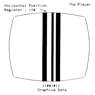
The final display will be a vertical green stripe at horizontal position 150, exactly matching the bit pattern in the graphics data register. Let's go ahead and run a program to do just this, so you can see what it looks like. Enter and run program 14.
5 REM **** DEFINES
10 HPOS0=53248
20 BITS0=53261
30 COL0=704
40 SIZE0=53256
100 REM **** PROGRAM 1
110 REM **** GENERATE A FIXED PLAYER
120 REM
130 REM **** SET HORIZ POSITION
140 POKE HPOS0,120
150 REM **** SET COLOR
160 POKE COL0,202:REM B,GRN,INTEN=10
170 REM **** SET DATA
180 POKE BITS0,218:REM 1011 0101
190 REM **** SET SIZE
200 POKE SIZE0,0
Program 14.
Let's modify the program to learn about the registers it uses. Let's change the color/luminance, the graphics data, and the horizontal position registers. The effect will be, respectively, changing the color of the stripe, the bit pattern of the stripe, and the stripe's horizontal position. Run programs 15, 16, and 17 to see these effects.
5 REM **** DEFINES
10 HPOS0=53248
20 BITS0=53261
30 COL0=704
40 SIZE0=53256
100 REM PROGRAM 4
110 REM **** SHIFT PLAYER COLORS
120 REM
130 REM **** SET HORIZ POSITION
140 POKE HPOS0,150
170 REM **** SET DATA
180 POKE BITS0,203:REM 1100 1011
190 REM **** SET SIZE
200 POKE SIZE0,0
300 REM **** SHIFT PLAYER COLOR
310 FOR PCOL=0 TO 255 STEP 2
320 POKE COL0,PCOL
330 NEXT PCOL
340 GOTO 310
Program 15.
5 REM **** DEFINES
10 HPOS0=53248
20 BITS0=53261
30 COL0=704
40 SIZE0=53256
100 REM **** PROGRAM 2
110 REM **** ROTATE A PLAYER
120 REM
130 POKE HPOS0,150:REM HORIZ POS
150 REM **** SET COLOR
160 POKE COL0,202:REM B GRN,INTEN=10
190 REM **** SET SIZE
200 POKE SIZE0,0
300 REM **** MODIFY BIT PATTERN
310 FOR T=0 TO 255
320 POKE BITS0,T
325 FOR DELAY=1 TO 100:NEXT DELAY
330 NEXT T
340 GOTO 310
Program 16.
5 REM **** DEFINES
10 HPOS0=53248
20 BITS0=53261
30 COL0=704
40 SIZE0=53256
100 REM **** PROGRAM 2
110 REM **** ROTATE A PLAYER
120 REM
150 REM **** SET COLOR
160 POKE COL0,202:REM B GRN, INTEN=10
170 REM **** SET DATA
180 POKE BITS0,203:REM 1100 1011
190 REM **** SET SIZE
200 POKE SIZE0,0
300 REM **** ROTATE RIGHT
310 FOR T=40 TO 200
320 POKE HPOS0,T
330 NEXT T
340 GOTO 310
Program 17.
There is also a "size" register. The size register tells CTIA how big to make the dots when it plots them on the screen, in horizontal terms. It can make them normal size, twice normal, or four times normal. All it does is plot the same dot one, two or four times before moving on to the next one. The stripe will grow to the right, with the left position remaining constant (this is because the left border is still at position 150, where CTIA starts the display). Run program 18 to see this particular effect. A 0 in this register means x1, a 1 means x2, and a 3 means x4.
5 REM **** DEFINES
10 HPOS0=53248
20 BITS0=53261
30 COL0=704
40 SIZE0=53256
100 REM **** PROGRAM 5
110 REM **** MODIFY PLAYER SIZE
120 REM
130 REM **** SET HORIZ POSITION
140 POKE HPOS0,120
150 REM **** SET COLOR
160 POKE COL0,202:REM B GRN,INTEN=10
170 REM **** SET DATA
180 POKE BITS0,203:REM 1100 1011
300 REM **** SHIFT PLAYER SIZE
310 POKE SIZE0,0
315 PRINT "SIZE NORMAL"
320 GOSUB 1000
330 POKE SIZE0,1
335 PRINT "SIZE X 2"
340 GOSUB 1000
350 POKE SIZE0,3
355 PRINT "SIZE X 4"
360 GOSUB 1000
370 GOTO 310
1000 FOR Z=1 TO 1000:NEXT Z:RETURN
Program 18.
The stripe is known as a "player". An object only 2 bits wide, but otherwise the same as a "player," is a "missile". Hence, the name "player-missile".
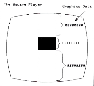
What good is a green stripe in the middle of the TV that does not even shut off when we press BREAK to quit running the program? We do not have to leave data in the graphics data register on all the time. Let's say we leave it all 0's for awhile, starting from the top of the screen. CTIA will plot only the usual playfield stuff and no player dots. But if we should suddenly put a 11111111 into that register, it will plot that in scan lines from there on. We can turn it off by putting the 0 back in that register, and we have a square sitting in the middle of the screen. It will really be a stripe, with a lit square in the middle of it, but to us, it will appear to be just a square (see Figure 22).
|
|
|
Figure 22. |
We could make the shape something other than a square by putting different data in the graphics control register. We could construct a space ship out of "slices" of bits, then feed them in one at a time, one slice per scan line. This way a player could be a spaceship on the screen, which is how Star Raiders works. We could move it horizontally by changing the horizontal position register, or vertically by changing where we start putting data in. And we will have this object on our TV screen. There are 4 available players and 4 missiles, all independent. A list of the control memory locations is shown on the next page.
This table lists a number of CTIA addresses, which can also be found in later discussions of the various hardware tables. Logically, since CTIA controls players, they should be CTIA addresses.
Missiles have the same colors as their players do. Missiles can be grouped together to form a fifth 8 bit player; four missiles 2 bits wide, positioned together, equal one player 8 bits wide. All missiles have the same data, which is usually 2 bits anyway.
Some of the above demo programs will now become clear. We set player 0's horizontal position to 150 by putting that value into the approximate register with a POKE statement. The color/luminance is bright green, intensity ten, and the graphics data information is CB hex or 203 decimal. We do not write the color/luminance information to the location listed above.
Remember back when we were doing display list interrupts and we talked about operating system shadow addresses? These are addresses the operating system maintains in RAM that are copied into the actual hardware addresses with each screen refresh. We found that the five playfield (not player) operating system shadow registers were copied into the hardware registers on CTIA, and our display list interrupts over-wrote that data a few scan lines down. The same thing applies to player-missile colors. If they are put directly into the hardware registers, the change will last just as long as the next refresh; less than a sixtieth of a second. You will see a very brief flash of color. If you would like permanent colors for your players, use the shadow registers.
Player-Missile Controls
You can also use a display list interrupt routine to change a player's color halfway through a refresh. The Atari people "shadowed" a good number of registers just for the ease of having the machine restore them to the original value at the beginning of the refresh. These shadow registers include the DMA controls, the pointers to where the display list is.
The information given so far is helpful. You can get some really neat color effects running players back and forth. Try program 19 for this effect and feel free to modify it in all sorts of ways. Note the effect when two player stripes run over one another, or when a player runs over a playfield object, such as a letter or a graphics mode dot.
This is known as a "collision". When two players or missiles or playfield objects have two "on" bits trying to get through CTIA at once, we have a priority conflict that needs to be resolved. CTIA must decide whether to let the player or the letter "shine through" when a letter is plotted beneath a player. The Atari actually has incredible flexibility, and gives you many different ways to set up priorities between players, missiles,and the playfield objects. The Atari also writes data to a "collision register" to let you know that a collision occurred. You can let the Atari's hardware worry about whether there's been a collision between your spaceship and a photon torpedo (your player and your missile). You no longer have to scan tables of X and Y co-ordinates in your program to see if they have collided. Instead, just look at the collision register every now and then.
20 REM DEMONSTRATES PRIORITY
30 POKE 623,2:REM P0 HIGHEST
40 REM POKE A 2 TO HAVE PLAYERS 2,3
50 REM HAVE LOWER PRIORITY THAN PLAYER 1
60 POKE 704,4:REM COLOR P0 GREY-LO
70 POKE 705,58:REM COLOR P1 ORANGE HI
80 POKE 706,90:REM COLOR P2 PURPLE-HI
90 POKE 707,196:REM COLOR P3 GREEN-LO
100 REM
110 POKE 53261,255:REM BITS P0
120 POKE 53262,255:REM BITS P1
130 POKE 53263,255:REM BITS P2
140 POKE 53264,255:REM BITS P3
150 PRINT "PLAYER 0 = GREY"
160 PRINT "PLAYER 1 = ORANGE"
170 PRINT "PLAYER 2 = PURPLE"
180 PRINT "PLAYER 3 = GREEN"
190 REM CYCLE THROUGH PRIORITIES
200 FOR X=1 TO 15
210 POKE 623,X
220 PRINT "PRIORITY CODE =";X
230 FOR T=36 TO 218 STEP 3
240 POKE 53248,20+T:REM PLAYER 0
250 POKE 53249,T:REM PLAYER 1
260 POKE 53250,218-T:REM PLAYER 2
270 POKE 53251,239-T:REM PLAYER 3
280 FOR Z=1 TO 15:NEXT Z
290 NEXT T
300 NEXT X
310 GOTO 200
Program 19.
Take for example the popular game Asteroids. On the Apple a horrendous amount of time is spent checking to see if a spaceship has collided with a rock, or a missile has collided with a rock, or a player, or another ship. That is what slows the Apple game down so much all that checking in the software takes a long time. In the Atari you do not need to. Just update the positions of the players and missiles, and check the collision registers. It will tell you all you need to know. In Star Raiders, missiles fired at the enemy are just players with high speed changes in the player data register. The enemy ships are other players, and collisions between them and missile players are checked in the hardware. That is why they run so fast.
You must select which priority scheme you would like to use with a POKE. There is a hardware location, which is located on the CTIA chip, but use the shadow register at 623 decimal instead.
Select either 8,4,2 or 1 to POKE. Adding those numbers gives wild results consisting of black regions where they overlap. (See the table below which cycles through all the different priority schemes.)
Add 10H to the number you POKE in (16 D) to let all missiles become the color of playfield 3. This way you can position them all together to be one object of the same color. Playfield 3 is not used frequently in playfield graphics, and this is why. The color is then made available for a fifth player, such as the ball in Atari Basketball.
Add 20H (32 Decimal) to have a different color (a logical OR) occur during overlap or collision.
"Play" refers to player. "P-F" refers to a playfield or display list generated, color register.
Use this priority chart after you have laid out your priorities and decided which object should be in front of another.
|
||||||||||||||||||||||||||||||
Player-Missile DMA
So far we have vertical stripes on the screen and some interesting color effects. If Basic was not fast enough to switch color registers in the middle of a screen refresh in the display list interrupts chapter, it is unlikely it can suddenly start doing it now. So we are stuck with assembly language and tying up the 6502 turning the graphics data on and off.
You need a thorough understanding of how players are generated to use really creative graphics. The people at Atari thought of the problems they would have with tying up the 6502. Remember that we did not want to tie the 6502 up doing display work. ANTIC was created to handle the tremendous memory access needs back then. The designers of the Atari used ANTIC to help with players and missiles as well.
Remember "DMA"? That is where ANTIC took over memory in order to satisfy the needs of CTIA in doing a screen refresh. You will recall ANTIC even elbows the 6502 out of memory to get to memory more quickly. This DMA is going on all the time whenever there is a screen refresh. Now there is a memory location we can write to, DMA CONTROL (DMACTL) which controls this DMA process.
Let's say we told the ANTIC chip to completely quit using DMA. The screen would go blank. ANTIC would no longer be forcefeeding CTIA and there would be no data to plot. But the 6502 would no longer be getting shut off by ANTIC, and would not lose so much time just sitting around waiting for ANTIC to finish up. It could continue running your Basic programs, at considerably higher speed, about 30-50% faster, depending on how much graphics data would otherwise be written. This is something to keep in mind if you ever have some serious amount of processing to do in slow Basic and would like some free processing time. If you were to set up a short, custom display list and memory, or just a few lines, ending with an instruction to wait for the next refresh, that would also help free up the 6502. The less data ANTIC must fetch from display memory, the more time is available for the 6502. You could have a display list as short as one graphics instruction.
Now most articles on player-missile graphics do not cover the basics, like POKEing the hardware registers directly. They rely strictly on Player-Missile DMA. It loses a lot of the concepts involved and takes away some of the other possibilities in players. Who needs P-M DMA to set up two stripes at either ends of the screen as paddles for a "Pong" game?
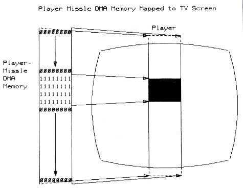
Let's set up a table in memory. It will be 256 bytes long. Each byte in memory will correspond directly to one horizontal scan line on the TV. (You will note that a player extends all the way off the screen, past where ANTIC and CTIA are generating playfield.) Now if we tell them, by enabling two "switches" (actually POKEs to DMA controls) we will no longer have to transfer data directly into the CTIA graphics register. CTIA will get the graphics data byte that corresponds to the particular scan line number from ANTIC. ANTIC will look at the table, decide what scan line we are currently on, and pass the byte on the table whose number matches the scan line number to CTIA. CTIA will use that byte to plot the player or missile on the screen. Once you set up the 256 byte table and switch ANTIC on, the 6502 is once again freed up to do something else. The Player-Missile Direct Memory Access (P-M DMA) is then completely automatic (Figure 23).
Using this method, an object is defined by a few "I" bits in this table which corresponds directly to the vertical stripe on the screen. If we turn on some bits, they will show up at the next refresh. If we move them upward in the byte table, the plotted object will move up. We control the horizontal position using the horizontal position register, the color using the color register, and control the size using the size register.
|
|
|
Figure 23. |
Now there are a lot of things you must do to initialize this DMA process. You have to reserve a location in memory for the 256 byte tables. You have to POKE into various DMA control locations, set colors, and so on. Rather than trying to list them one by one, let's just take a working example and go over it to show how it works.
Let's look at Program 20 for a fine example of DMA use for P-M graphics.
Line 30 contains a POKE to an operating system location which instructs the system to work with a normal size playfield; i.e. 40 characters across. The location is a shadow register for a hardware register on ANTIC named DMACTL. There are two electrical switches that need to be turned onto allow P-M DMA to begin, and this is one of them. This one controls all of DMA, not just Player-Missile. The other switch is called GRACTL.
10 DIM A$(10),B$(100)
20 GRAPHICS 8
30 POKE 559,62
40 POKE 53248,120
50 POKE 704,88
60 I=PEEK(106)-8
70 POKE 54279,I
80 POKE 53277,3
90 POKE 53256,3
100 J=I*256+1024
110 FOR Y=J+120 TO J+137
120 READ Z
130 POKE Y,Z
140 NEXT Y
150 FOR X=48 TO 221:GOSUB 500:NEXT X
160 GOTO 150
320 POKE Y,Z
500 POKE 53248,X
510 RETURN
600 DATA 60,60,60,60,60,60
610 DATA 255,255,255,255,255,255
620 DATA 60,60,60,60,60,60
Program 20.
Line 40 is a POKE to the horizontal position register for Player 0, putting the player at 120. Line 50 is a POKE Player 0's shadow color register for a pink color. We need 256 bytes for our DMA table for Player 0. We must run all the players and missiles with DMA, so we need considerably more than 256 bytes. The total comes out to 2048 bytes for our "bitmaps" of the players.
We need to find a place in free memory to put this 2048 bytes. Remember when we were using alternate character sets that required 1024 bytes? We modified the top of the memory pointer, located in location 106, and moved it back to make sure we had an area of memory the Atari would not use. We will do the same thing here, moving the pointer back 8*256 or 2048 bytes back.
We then POKE the memory page number (address/256) into a location called PMBASE. This tells ANTIC where to start fetching data for CTIA.
|
|
|
Figure 24. |
We POKE a location called GRACTL, for GRAphics ConTroL register. GRACTL is the second of two switches that has to be turned on to enable P-M graphics. We POKE a 3 into there to tell ANTIC and CTIA to start using P-M DMA. We POKE player 0's size register at 53256 with a 3 to make our player 4 times normal size.
Our Player is now being plotted on the screen. Whatever junk is in memory at this point is now busily being pulled out of memory by ANTIC and fed to CTIA. The area of memory we are using is empty. The Graphics instruction at the beginning of the program, before we moved the memory pointer back, cleared it out for us. We should put some sort of bit pattern into memory to create a display. The program does that next.
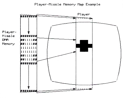
Line 280 sets J equal to I (which is the start of the P-M table) * 256 (because that value was in 256 byte pages.) J points to the beginning of the P-M table in memory. We add 1024 to it, the Player 0 data is 1024 bytes from the beginning of the table, with the other players and missiles around it. The table looks like the example shown to the right.
There is also a P-M DMA mode where only 1024 bytes are used, 128 per player. In this mode each byte represents not one but two scan lines. This is known as a "double line resolution" in the manuals. Just adjust the addresses above for half as much data.
J now equals the beginning of the Player 0 bit map data. The FOR loop in the program runs from J+120 to J+137, for 18 lines in the middle of the screen. Data is read in and copied into those bytes. This data is in the form of a "Cross", where the 60's on top and bottom are: 00111100 and the 255's are: 11111111. This data will be sent to the screen in the form of dots for 1 bits and blanks for 0 bits, so at this point we have a cross on the screen, still in pink. We have a loop which pokes the horizontal position register from 48 to 221, and starts over at 48 again. This will move our player stripe, with the cross in the middle of it, across the screen (see Figure 24).
There should not be a lot of mystery left in players and missiles now. ANTIC is just POKEing our CTIA graphics data registers for us. This helps free up the 6502. We move the player horizontally with a POKE, vertically by copying bits in this table up and down, and select color and size with POKEs. We will learn how to read collisions later.
|
|||||||||||||||||||||||||||||||||||||||||||||||||||||||||||||||||||||||||||||||||||||||||||||
|
|||||||||||||||||||||||||||||||||||||||||||||||||||||||||||||
|
Player-Missile Controls |
|||||||||||||||||||||||||||||||||||||||||||||||||||||||||||||
Table of Contents
Previous Section: Display List Interrupts
Next Section: Character Sets