3

Dimensioning Strings
for PMG
In this chapter you'll learn an important secret--one not revealed in most other books and articles on PMG.* The secret is to use strings to store PM (Player-Missile) data. [If you don't know what a string is or how to dimension it, I suggest you see Inside ATARI BASIC by William Carris (Reston, Va.: Reston Publishing Company, Inc., 1982.]
Why is this such a big deal? Because (as I mentioned earlier) Atari has the ability to move string data super fast. So by using strings you can achieve fast vertical animation without resorting to machine language! Without using strings, vertical moment in BASIC is slow and jerky.
*I'd like to thank Sheldon Leemon for his excellent article on how to use strings for fast PMG animation: "Take Apart: Outer Space Attack," Softside Magazine, March 1982.
DIMENSIONING STRINGS FOR PMG
Using this approach, you dimension a separate string at the beginning of your program for each of your "players." Also, you dimension one string for the missile area. In dimensioning these strings, there are certain rules you must keep in mind.
THE BUFFER STRING
One rule is that the beginning of PM memory is not used to display graphic images directly. That is, data in this beginning area are not automatically displayed on the screen. In this book, we will call this beginning area of PM memory a buffer.
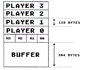
If you want, you can store player image data in the buffer and then move it to the display area whenever you want to. Here's a diagram that shows the PM memory area. See if you can distinguish between the buffer and display areas.

Note that this diagram shows the PM memory organization for what is called double-line resolution. Double-line resolution simply means that two lines are used to display each byte in PM memory. That is, if a bit is set to "1," then two pixels (one underneath the other) are lit up. We'll talk about double-line resolution in more detail later. Just remember that this diagram is for double-line resolution. Later we'll discuss single-line resolution (see Chapter 9).
- Study the diagram. Then answer these questions.
1. How big is the buffer area at the beginning of the PM memory area?
2. In double-line resolution, how many bytes are set aside for each player?
3. Where does the PM display area start?
- 384 bytes past the beginning of the PM memory area.
- At the very beginning of PM memory area.
- Neither a nor b.
|
||||||
One important rule, then, is that when using double-line resolution, you must have a 384-byte buffer at the beginning of the PM memory area. This buffer area is not used to turn on screen pixels. That is, if a bit is set to "1" in this area, there will be no direct effect on what is displayed on the screen. That's why we say the actual PM display area starts 384 bytes after the beginning of the PM memory area.
Another important rule is that when you are using double-line resolution, the PM memory area must start on what is called a "1K boundary." If you know what I mean by "1K boundary," you can skip to "Starting on a 1K Boundary." Otherwise, read on and I'll explain.
1K BOUNDARY
A 1K boundary is simply a location in memory that can be divided evenly by 1K (1K = 1024 bytes). For example, 2048 is on a 1K boundary because 1024 goes into 2048 evenly two times.
-
Which of these are on a 1K boundary?
a. 4096
b. 3073
c. 3072
|
||||||
STARTING ON A 1K BOUNDARY
To get your Player-Missile Base Register (PMBASE) to start on a 1K boundary, you need to do some calculations. That's because the first string you define won't automatically start at any given point in memory. There are different ways to find a 1K boundary. The method I recommend is to dimension some "filler strings" to take up space until the 1K boundary is reached. Here is some code you can use to define these "filler" strings. Take a moment to look it over.
DIM FILLER1$(1),FILLER2$((INT(ADR(FILLER1$)/1024)+1)*1024-ADR$(D$)-1)
Note: When typing this code into your computer, you would normally enter it as one continuous line. I've broken it into separate lines here to make it easier to read.
You don't really need to understand this filler code. All you need to know is that it takes up string memory until a 1K boundary is reached. But, if you like, I'll explain; otherwise, you can skip ahead to "Setting Up PM Memory."
UNDERSTANDING THE FILLER CODE
Since you're so interested in the filler code, I'll rewrite it for you in a slightly different way so it's easier to understand:
10 DIM FILLER1$(1)
20 BOUNDARY=INT(ADR(FILLER1$)/1024+1)*1024
30 LENGTHFILLER2=(BOUNDARY-ADR(D$)-1
40 DIM FILLER2$(LENGTHFILLER2)
Let's examine this code line by line, starting with line 10:
10 DIM FILLER1$(1)
In line 10 we define our first filler string, which we call FILLER1$. We do this so we have a reference point, to know where the beginning of string memory starts.
20 BOUNDARY=INT(ADR(FILLER1$)/1024+1)*1024
In line 20 we calculate the address of the next 1K boundary above the address of FILLER1$. We do this by dividing the address of FILLER1$ by 1024, adding 1 and throwing away the remainder. Then we multiply that answer by 1024. (INT "throws away the remainder." ADR gives us the address of FILLER1$.)
Let's apply this code to a simple example. Suppose the address of FILLER1$ is 2040. We divide 2040 by 1024 and get 1.992. We add 1 to 1.992 and get 2.992. We throw away the remainder (.992) and get 2. Then we multiply 2 by 1024 to get 2048, which is the 1K boundary above 2024.
30 LENGTHFILLER2=(BOUNDARY-ADR(D$)-1)
In line 30 we simply subtract the address of FILLER1$ from the 1K boundary and then subtract 1 from that. We subtract 1 because we want FILLER2$ to fill up space right up to (but not over) the 1K boundary.
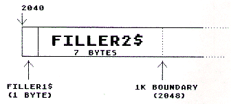
We still need to find the length of our second string, namely FILLER2$. If we subtract the address of FILLER1$ from the next 1K boundary, we would get 8, since 2048 - 2040 = 8. But to get the proper length for FILLER2$, we need to subtract 1 from 8 (since we want to take up space just up to the 1K boundary). Look at this diagram:

- Suppose that the address of FILLER1$ were 2030. What would the proper string length be for FILLER2$?
|
||||||
This finishes our explanation of the filler code. Now let's go on to the next step.
SETTING UP PM MEMORY
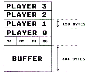
After dimensioning the filler strings, the next step is to allocate space for the PM memory by dimensioning additional strings. Let's look again at the way PM memory is organized so you can see what PM strings will be needed:

- Based on this diagram, which string do you think we should define first?
a. BUFFER$
b. MISSILES$
c. PLAYER0$
|
||||||
It's important to determine the BUFFER$ string immediately after the filler strings. That way the buffer will start on a 1K boundary. For example:
10 DIM FILLER1$(1),FILLER2$((INT(ADR(A$)/1024+1)*1024-ADR(FILLER1$)-1)
20 DIM BUFFER$(384)
- Actually, line 20 isn't finished yet. Can you explain why?
|
||||||
In doing this, we use one string for all of the missiles and a separate string for each of the players.
- With this in mind, see if you can finish line 20:
20 DIM BUFFER$(384)
|
||||||
Of course, you could use different variable names, such as M$ for MISSILES$, or P0$ for PLAYER1$, and so on. Also, notice that there is only one string defined for all four missiles.
PLAYER NUMBERING
Notice that the players are numbered from zero to three. Does that seem a little strange to you? (It does to me!) Actually, you can name the players any way you want to. This kind of naming convention is often used by assembly language programmers. It really means that PLAYER0 starts 0 bytes from the beginning of the player area. Similarly, the name "PLAYER1" means that the player is located 1*128 or 128 bytes from the beginning of the player area. Similarly, PLAYER2 is located 2*128 or 256 bytes from the beginning of the player area.
That's quite a mouthful I know. Let's see if I got the message across:
- Suppose you know that the beginning of the player memory area starts on byte 4480. Where would PLAYER1 start?
|
||||||
- Again, assuming the player memory area starts on byte 4480, where would PLAYER3 start in memory?
|
||||||
You now know how to allocate space for the PM memory area using double-line resolution. Later you'll learn how to do a similar setup for single-line resolution. That will be easy since you've already learned the fundamental concepts involved. Now that we've defined our player image and allocated space for PM memory, let's get a player on the screen!
Return to Table of Contents | Previous Chapter | Next Chapter

