Game paddles can make arcade-style games like car racing simulations, tennis, and Ping-Pong more realistic and fun. Unlike joysticks, game paddles are analog devices. While joysticks provide the computer with either on or off signals, paddles provide the computer with a varying signal.
A paddle contains a resistor with a variable amount of resistance and a switch in one case. The switch acts as the fire button and operates like the fire button on a joystick. The electrical resistance of the paddle depends on the position of the variable resistor, often referred to as a potentiometer, or pot. When the pot is turned all the way in one direction, the resistance measured between the potentiometer's side and middle leads is 0 ohms. When the shaft is turned in the opposite direction, the resistance is about 500K ohms on Commodore paddles. Atari paddles require a resistance of about 1M (1 million) ohms.
When paddles are used, current from the computer flows through the potentiometers. The amount of current that flows depends on the resistance in the pot. The greater the resistance, the less current flow. The opposite is also true-the less the resistance, the greater the current flow.
By turning the knob of the potentiometer, the voltage, measured across the leads of the potentiometer, varies between 0 volts (ground) and +5 volts. The computer senses this voltage and uses it to determine a value for the position of the potentiometer.
This voltage, which is an analog value, must be converted to a digital value to be used by your computer. Analog-to-digital converters, sometimes called A/D converters, were once very expensive. Fortunately, your computer has this hardware built in. Using its analog-to-digital converter, your computer interprets the voltage across the variable resistor of the paddle as a number between 0 and 255 (1 to 228 for the Atari). This value is kept in special memory locations in your computer. For the Commodore 64 and 128, these memory locations are 54297 and 54298 ($D419 and $D41A in hexadecimal). In the VIC-20, locations 36872 and 36873 ($9008 and $9009) are used. For the Atari computers, it's not necessary to PEEK the actual memory locations-Atari BASIC has a command, PADDLE(X), which lets you see the values returned for the paddle positions. The value of X in this Atari statement is 0 or 1 (a different X for each paddle), provided the paddles are plugged into control port 1.
To build your own pair of game paddles, you'll need the following parts:

|
Here's how to put your game paddles together: |
||||||||||||||||||||||||
|
1. Cut eight pieces of stranded copper wire
about 24 inches long and remove about 1/4 inch of insulation from each
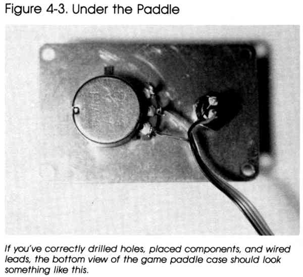
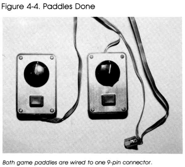
end. 2. Connect one end of two of the wires to pin 7 of the 9-pin plug. 3. Connect another two wires to pin 8 of the plug. 4. Solder the remaining four wires to pins 3, 4, 5, and 9. 5. Remove the cover from one of the plastic boxes and drill two holes as in Figure 4-1. One hole is for the potentiometer, while the other is for the switch. Drill a hole in one end of the plastic case for the wires. Repeat these steps for the second plastic box. 6. Mount the switches and potentiometers in their respective holes. Attach the knobs to the shafts of the potentiometers. 7. Take one wire from pin 7, one wire from pin 8, the wire from pin 3, and the wire from pin 9 of the 9-pin plug to one of the paddle boxes. Pull the wires through the hole in the top end of the box. Turn the box cover with the potentiometer and switch mounted on it over so that their leads are facing up (as shown in Figure 4-1). 8. Connect the wire from pin 8 to one lead of the switch. Solder the wire from pin 3 to the other switch lead. The wire from pin 7 should be soldered to the left side lead of the potentiometer, and the wire from pin 9 is connected to the middle lead of the potentiometer. Mount the cover on the box. One paddle is completed. 9. The procedure for the second paddle is identical, except the wires are from pins 7, 8, 4, and 5 of the 9-pin plug. The wire from pin 8 connects to one lead of the switch. The other switch lead is connected to the wire from pin 4. The wire from pin 7 connects to the left lead of the potentiometer, and the remaining wire, from pin 5, connects to the middle lead. Close the plastic box, and your second paddle is finished. |
||||||||||||||||||||||||


|
To try out your paddles, turn off your computer
and plug the paddles' 9-pin connector into control port 1. Turn on the
computer, then type in and run the appropriate version of Program 4-1. Program 4-1-Commodore 64/128 EF 10 POKE56333,127:REM IRQ OFF HH 20 POKE56322,192:REM SET BITS 6,7 OF {SPACE}DATA DIRECTION REGISTER FOR OUTPUT EC 30 POKE56320,64:REM 128 FOR PORT 2 HG 40 X=PEEK(54297) DJ 50 Y=PEEK(54298) XE 60 POKE56322,255:POKE56333,129:REM RESTORE REGISTERS DG 80 PRINTX,Y SJ 100 GOTO10 Program 4-1-VIC-20 GD 10 PRINT1-(PEEK(37151)AND16)/16;PEEK(36872); RG 20 POKE37154,127:PRINT1-(PEEK(37152)AND128)/128; :POKE37154,255 PS 50 PRINTPEEK(36873) BD 60 GOTO10 Program 4-1-Atari 10 PRINT PADDLE(0);" ";PADDLE(1) 20 GOTO 10
Download (Saved BASIC)
When you run the appropriate program, two columns
of numbers should appear on the screen. Each column of numbers corresponds
with a paddle. As you turn the knobs of the paddles, the numbers should
vary between 0 and 255 for the Commodore computers, and between 1 and 228
for an Atari computer. |
|
|
The following ML routine (Program 4-2) works
only on the Commodore 64 or Commodore 128 in 64 mode. The routine is POKEd
into the cassette buffer and can be called by typing SYS 828 anytime you
want to read the paddles. It's a simple matter to incorporate this routine's
BASIC loader (omit line 40) into any program you write which requires paddle
reading. To read a paddle value after calling the routine with SYS 828,
simply PEEK the appropriate location:
Program 4-2. ML Paddle Reader MF 10 I=828:AD=251 HG 20 READ A:IF A=256 THEN40 RG 30 POKE I,A:I=I+1:GOTO20 QA 40 SYS 828:PRINTPEEK(AD);PEEK(AD+1);PEEK(AD+2); PEEK(AD+3):GOTO40 RF 50 DATA 76,63,3,162,1,120,173 KH 60 DATA 2,220,133,167,169,192,141 SX 70 DATA 2,220,169,128,141,0,220 EE 80 DATA 160,128,234,136,16,252,173 DS 90 DATA 25,212,149,251,173,26,212 CD 100 DATA 149,253,169,64,202,16,232 FP 110 DATA 165,167,141,2,220,88,96,256 |
Return to Table of Contents | Previous Chapter | Next Chapter