APPENDIX E
GTIA
The GTIA is a new display chip that will someday replace CTIA. Actually it is nothing more than a CTIA with a few more features. It simply provides three additional modes of interpretation of information coming from the ANTIC chip. ANTIC does not require a new mode to talk to GTIA; instead, it uses the high resolution mode $F. GTIA is completely upward compatible with the CTIA. A brief summary of CTIA's features follows so that the differences between CTIA and GTIA can be presented.
The CTIA is designed to display data on the television screen. It displays the playfield, players and missiles, and detects any overlaps or collisions between objects on the screen. CTIA will interpret the data supplied by ANTIC according to six text modes and eight graphics modes. In a static display, it will use the data from ANTIC to display hue and luminance as defined in one of four color registers. The GTIA expands this to use all nine color registers or 16 hues with one luminance or 16 luminances of one hue in a static display.
The three graphics modes of GTIA are simply three new interpretations of ANTIC mode $F, a hi-resolution mode. All three modes affect the playfield only. Players and missiles can still be added to introduce new hues or luminances or to use the same colors and luminances in more than one way. All displays of hues and luminances can still be changed on-the-fly with display list interrupts. The GTIA uses four bits of data from ANTIC for each pixel, called the pixel data. Each pixel is two color clocks wide and one scan line high. Thus, the pixels are roughly four times wider than their height. The display has a resolution of 80 pixels across by 192 down. Each line then requires 320 bits or 40 bytes of memory, the same number of bytes used in ANTIC mode $F. Therefore for a program to run the GTIA modes it must have at least 8K of free RAM for the display.
The GTIA modes are selected by the priority register, PRIOR. PRIOR is shadowed at location $26F hex by the OS and is located at D01B hex in the chip. Bits D6 and D7 are the controlling bits. When neither is set there are no GTIA modes and GTIA operates just like CTIA. When D7 is 0 and D6 is 1, Mode 9 is specified which allows 16 different luminances of the same hue. Remember the pixel data supplied by ANTIC is four bits wide which means 16 different values can be represented. Players and missiles can be used in this mode to introduce additional hues. When D7 is 1 and D6 is 0, Mode 10 is specified. This mode gives nine colors in the display by using the four playfield color registers plus the four player/missile color registers plus the one background color register. When players are used in this mode, the four player/missile color registers are used for them also. When D7 is 1 and D6 is 1, Mode 11 is specified. This mode gives 16 hues with the same luminance again because 16 different values can be represented by four bits. Players and missiles can be used in this mode to introduce different luminances.
PRIOR
| D7 | D6 |
| D7 | D6 | OPTION | |
|---|---|---|---|
| 0 | 0 | No GTIA modes (CTIA operation) | (Modes 0-8) |
| 0 | 1 | 1 Hue, 16 Luminances | (Mode 9) |
| 1 | 0 | 9 Hues/Luminances | (Mode 10) |
| 0 | 0 | 16 Hues, 1 Luminance | (Mode 11) |
Figure E-1
Bit Pattern in PRIOR selects GTIA
Setting up the new GTIA modes is as simple as setting up the present modes used in CTIA. To implement the modes from BASIC simply use the commands GRAPHICS 9, GRAPHICS 10, and GRAPHICS 11 for Mode 9, Mode 10, and Mode 11 respectively. In Assembly Language selecting one of these modes is identical to opening the screen for any of the other modes. If you are building your own display list then PRIOR must be set to select the correct mode as in Figure E-1.
Mode 9 produces up to 16 different luminances of the same hue. ANTIC provides the pixel data which selects one of 16 different luminances. The background color register provides the hue. In BASIC this is done using the SETCOLOR command to set the hue value in the upper nybble of the background color register, and to set the luminance value in the lower nybble to all zeroes. The format of the command is
SETCOLOR 4,hue value,0
where 4 specifies the background color register, "hue value" sets the hue and can be anything from 0 to 15, and 0 will set the luminance part of the register to zero. This has to be done because the pixel data from ANTIC will then be logically OR'ed with the lower nybble of the background color register to set the luminance that appears on the screen. The COLOR command is then used to select luminances for drawing on the screen by using values from 0 to 15 as its parameter. So a BASIC program will include at least the following statements to use Mode 9:
GRAPHICS 9          to specify Mode 9
SETCOLOR 4,12,0     to Initialize the background color
                    register to some hue, In this case green.
FOR I=0 TO 15       some method where
COLOR I             the COLOR command Is used
PLOT 4,I+10         to vary luminance.
NEXT I
In Assembly Language use the OS shadow for the background color register $2C8 to set the hue in the upper four bits with hex values from $0 to $F. If CIO calls are used, store the pixel data into the OS register ATACHR located at $2FB. This selects the luminance with hex values from $0 to $F. If you are maintaining your own display data then the pixel data goes directly into the left or right half of the display RAM byte.
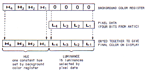
Figure E-2
Background Color Register OR'ed with pixel data to give final color.
Mode 11 is similar to Mode 9 except that it provides 16 different hues all with the same luminance. Again ANTIC will provide the pixel data to select one of 16 different hues. In BASIC the SETCOLOR command is used to set up the single luminance value in the lower nybble of the background color register, and in the upper nybble, the hue value will be set to all zeroes. The format of the command is
SETCOLOR 4,0,luminance value
where 4 specifies the background color register, 0 sets the upper nybble to zero and "luminance value" sets the value of the luminance and can range from 0 to 15. As with the other graphics modes (except Mode 9), the first bit of the luminance is not used, so effectively only even numbers result in distinct luminances which gives eight different possible luminances in this mode. The COLOR command is used in this mode to select the various hues by using values from 0 to 15 in its parameter. The pixel data from ANTIC will be logically OR'ed with the upper nybble of the background color register to set the hue part of the value that ultimately generates the color on the screen. So a BASIC program using Mode 11 will include at least the following statements:
GRAPHICS 11         to specify Mode 11
SETCOLOR 4,0,12     to initialize the background
                    color register to some luminance,
                    in this case very bright
FOR I=0 TO 15       some method where the
COLOR I             COLOR command is used
PLOT 4,I+10         to vary the hue
NEXT I
In Assembly Language use the OS shadow for the background color register $2C8 to set the luminance in the lower four bits with hex values from $0 to $F. If CIO calls are used, store the pixel data into ATACHR located at $2FB. This selects the hue with hex values from $0 to $F. If you are maintaining your own display data then the pixel data goes directly into the left or right half of the display RAM byte.
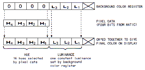
Figure E-3
Background Color Register OR'ed with pixel data to give final color.
Mode 10 will allow all nine color registers to be used in the playfield at one time. Each color register to be used must be set to some combination of hue and luminance. The pixel data from ANTIC is used in this mode to select one of the color registers for display. In BASIC the SETCOLOR command can be used as described in the BASIC Reference Manual to set the colors in the background and the four playfield registers. These can also be set by using the POKE instruction to addresses 708-712 where the four playfield registers and the background register are located. The POKE instruction must be used to set the four player/missile color registers at locations 704-707. The COLOR command is used to select the color register desired. The only meaningful values for its argument are 0 to 8. A problem arises with this mode. ANTIC supplies four bits of data per pixel, as it does with Modes 9 and 11. This allows for the selection of 16 color registers. However, only nine color registers exist in the hardware. An illegal data value between 9 and 15 will select one of the lower value color registers. A BASIC program using mode 10 will include:
- a GRAPHICS 10 command to specify Mode 10;
- a set of POKE instructions to put hues and luminances into the color
registers,
OR a combination of SETCOLOR commands and POKE instructions to do that; - a COLOR command to select the desired color register.
In Assembly Language, store the pixel data in ATACHR ($2FB) or directly into the display RAM byte as in Modes 9 and 11. In this mode the pixel data can range from 0 to 8 and selects one of the nine color registers.
| COLOR STATEMENT VALUE |
COLOR REGISTER USED |
OS SHADOW |
|---|---|---|
| 0 1 2 3 4 5 6 7 8 |
D012 D013 D014 D015 D016 D017 D018 D019 D01A |
2C0 2C1 2C2 2C3 2C4 2C5 2C6 2C7 2C8 |
Figure E-4
Color Register numbers and locations and COLOR command reference.
An important question arises in conjunction with GTIA concerning compatibility. GTIA is fully upward compatible with the CTIA and all software that runs on a CTIA system will run the same way on a system with GTIA. This means you still have the full use of players and missiles, still have collision and overlap detection and display list interrupts. The GTIA graphics modes are fully supported by the OS and all graphics commands and utilities that run in the CTIA modes can be used in GTIA modes.
More colors are available to display at one time on the screen. Sixteen color changes can occur on one line totally independent of processor intervention. This is actually better than what could be done with display list interrupts which could give at most only 12 color changes per line. Much finer contour and depth can be represented using the shading available in Mode 9. This means three dimensional graphics can be realistically displayed.
On the other hand, there are some disadvantages. GTIA modes are map modes, there can be no text displayed in these modes. A custom display list must be used to switch to a mode that supports character displays. The GTIA pixel is a long, skinny horizontal rectangle (4:1, width to height) and does not represent curved lines well. Because each pixel uses four bits of information, GTIA requires nearly 8K of free RAM to operate. Although it is upward compatible, it is NOT downward compatible. Thus programs which use GTIA modes will NOT produce correct displays on computers that have CTIA's. They may well be recognizable but will not be as colorful. There is no way currently for a program to determine whether or not a GTIA is present in a system. Finally, color artifacts produced by a GTIA system will not be identical to the color artifacts produced on the same television with a CTIA system.
Return to Table of Contents | Previous Chapter | Next Chapter