Build Your Own Light Pen
John Anderson
In this article, we'll take stock of a promising, yet somehow neglected input device for the Atari computer: the light pen. We will look at the capabilities of such a device, and review a pen available for the Atari as well as other machines. We shall go on to outline steps involved in the construction of an inexpensive but fully functional pen, using readily available parts.
If light pens don't sound to you like a topic that should necessarily elicit heated controversy or a complex and somewhat absurd tale, you are justified, but incorrect. Remember, you own an Atari, so anything is possible. Read on.
In the atmosphere of inspiration that couched the design of the Atari 400/800 computer, foresighted engineers built a great many capabilities directly into the hardware of the machine. Among these was the capability to support a light pen without the need for any additional controller boards. Even today, not too many other machines can make this claim. A light pen can be quite simply plugged into controller port 0, as if it were a paddle or joystick. It can be read straightforwardly with the statements PEEK(564) and PEEK(565). And that is all there is to it. That is, from an engineering point of view, you understand.
Those with machines of recent acquisition may not be aware that at one time Atari itself slated a light pen for production. It was to cost less than $100. In the second quarter of 1981, a products brochure that showed the device in use was released. It was a stubby, fat hunk of plastic with a tip switch on it. And what pretty multicolor pictures it supposedly drew.
Mail-order houses, as they are wont to do, accepted back orders on the Atari pen for some time. Though the decision to kill it was made over a year ago, the product was listed in a few retail rosters until only a few months ago.
At some point during its short development, a decision was made to pull the pen. The reasons for this remain somewhat vague. Some have suggested that the tip switch was flaky, making the device unreliable.
Another explanation I have heard from more than one reliable source goes like this: The Atari is designed as the machine for everybody, including novices and kids. Marketing was skitterish about the idea of a tiny kid fooling around a TV tube with a big pointy stick. One false move and gazonga: Mommy finds Billy on the living room floor, a victim of implosion! "Think of the lawsuits," said the legal department. "Pull the pen," said marketing.
Stop laughing. This may or may not have been the last straw concerning the Atari light pen. Whether it was or not, the pen was pulled from production very swiftly, and it is unlikely the decision will ever be reversed. A few did manage to get off the assembly line, however, and the few people who own them quite properly regard them as collector's items.
Hobbyists like myself, who have read about the capabilities of light pens and know also of the built-in pen capabilities of Atari machines, awaited the appearance of Atari-compatible light pens from other sources. Surprisingly, at least to me, no cheap pen has become available in the ensuing time. It is too bad, really. The peripherals can do a lot to make a microcomputer friendlier.
Just how can they do this? Kind of you to ask. First, let's find out what they do.
Light On The Subject
A light pen, when touched to or aimed closely at a connected monitor or TV screen, will allow the computer to determine where on that screen the pen is aimed. The driver program may subsequently take that information and do various things with it, but the job of the pen itself is quite simply to make a time measurement, which will be translated into x and y coordinates representative of a position on the CRT.
|
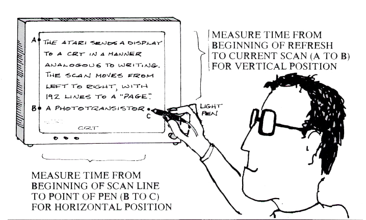
The capability may seem remarkable, and it is, though a simple explanation of how it works may dispel some of the awe. You may be aware that a TV or raster monitor typically refreshes at a rate of 60 frames per second. That is to say the electron gun or guns draw 60 pictures on the screen in one second. But it is impossible to draw an entire picture at once. Rather, the picture is drawn by the scan line, starting in the upper left-hand corner, moving to the right. When a line is completed, work begins on the next line. The Atari standard is 192 scan lines per frame. (An excellent explanation of this mechanism was provided by David Small in the June and July 1981 issues of Creative.)
Now let's imagine we have a special kind of transistor: one that is sensitive to light. We have hooked this transistor to our Atari, and aimed it at a point on the screen. By noting when a scan goes by and measuring the interval between scan lines or entire screen refreshes, we can get a good idea where the phototransistor is pointed on the video screen. The pen then allows us, through software, to generate x and y vectors corresponding to a point on the screen, which we may then use to draw pictures, make a choice from a menu of alternatives, or answer questions put to us by a program. Figure 1 is a simplified diagram of the process.
|
As opposed to input via the keyboard or even a paddle or joystick, a light pen can be a dramatically friendly peripheral. Imagine needing merely to point the device at your choice on the screen, in order to make that choice. Or to draw a picture on your CRT as straightforwardly as you might use a crayon on a piece of paper. These are the kinds of possibilities a light pen affords.
By the way, you would have to work extremely hard to push a light pen through a CRT. It just isn't something you could do without extreme effort, assuming you could do it at all.
Mightier Than The Sword
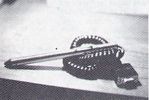
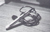
Soon after the Atari pen bit the dust, a third-party pen for the Atari appeared from Symtec Corporation. This pen is about the most professional you can find for any machine. It is, in fact, an adaptation of the same model used in professional mini and mainframe operations. Its barrel is of heavy, extruded aluminum, with a coiled telephone handset wire leading to an Amphenol connector. It includes a sensitivity trimmer adjustment. Everything about the Symtec pen is top of the line, including the $150 price tag.
Figure 2 provides an example of the drawing capabilities of the Symtec pen. The software driver I used to create the caricature (portrait) of our fearless leader, Mr. Ahl, appears as Figure 3. In ten lines, the code evidences how elementary a driver can be. This is an obvious benefit of the fact that so much of the work is already done in hardware.
|

10 GRAPHICS 7+16
20 SETCOLOR 4,0,14:COLOR 3
30 X=PEEK(564)
40 IF X<70 THEN X=X+230
50 Y=PEEK(565)
60 IF Y<17 OR Y>112 THEN 50
70 X=X-75:Y=Y-14
80 IF X<0 OR X>159 THEN 30
90 TRAP 30:IF STICK(0)=15 THEN PLOT X,Y
100 GOTO 30
Figure 3.
If you wish to endow your Atari with professional light pen capability, the Symtec pen is literally without rival on the market. The pen is also available for the Apple, IBM PC, and VIC20 machines. For more information, contact Symtec, 15933 West 8 Mile, Detroit, MI 48235. (313) 272-2952.
Penlight Light Pen
Of course, many Atari hobbyists will be unable to budget that kind of money for a light pen purchase. I believe the market exists for an inexpensive pen, but no company has yet stepped forward with such a product. Other inexpensive pens, for machines such as the Apple and TRS80, can be modified for use with the Atari. I reasoned, however, that it wouldn't entail very much more work to start from scratch. It would also be much cheaper.
|
The result: for a couple of hours work and about $10 worth of hardware, you can put a homemade Atari light pen to work with your system. While it will have neither the accuracy nor the feel of the Symtec pen, it will be perfectly serviceable for many applications, and loads of fun to play with. It is also easy to make. So let's make one!
First, you've got to stock some parts. Get down to the nearest Radio Shack, and pick up the following: one phototransistor, model number 276-130, 89 cents: 1/2 watt 100K ohm resistor, model number 271-045, 19 cents for two: penlight, model number 61-2626, $1.99.
You will also need a few other pieces of paraphernalia. These include: DE-9 connector plug for the controller port on the Atari, and five-conductor shielded cable (you cannot use an existing Atari joystick, as it lacks necessary pin-outs); a couple of feet of insulated bell or stranded wire; and the plastic top to a Bic pen. You may also want a grommet or strain relief for the pen top.
For tools, you'll need this array: low wattage soldering iron and solder; wire cutters (needlenose pliers are handy too); X-acto or razor knife; scissors or reamer; small flat blade and Philips screwdrivers; long stick pin or safety pin; and insulating electrical tape.
Got these things together? Let's get going. First, unscrew the cap on the penlight, and disassemble the light bulb and bayonet assembly from the white plastic pen tip. Next, gently press the switch assembly down through the barrel of the pen with the Philips screwdriver. We don't want a penlight anymore, and we need all the real estate inside it in order to convert.
|
The cable we connect will feed through the hole where the on/off switch used to reside. You will pop the switch out through the open side of the barrel, along with two springs and a black plastic retaining collar. When these things have been pushed out, the barrel will be empty, and that's the way we want it.
Using a closed pair of scissors or a reamer, enlarge the switch hole on the metal barrel top until it accommodates the wire, grommet, or strain relief on the connector wire you have chosen. When this is accomplished, push the pen barrel onto the wire (it would be embarrassing to construct the entire pen, then discover you left the barrel aside, and have to disassemble all your work to fit it on).
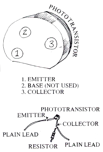
Take the phototransistor, and hold it so that the bottom is facing you. Turn it until it is oriented along the lines of the diagram presented as Figure 4. This will indicate the positions of collector, base, and emitter leads of the component. You can clip the base lead short, as we will not be making use of it.
Solder directly to the collector lead one 100K resistor, along with a plain lead about four or five inches long, as indicated in Figure 4. Solder another lead of about the same length to the emitter lead, also as indicated. Don't use a high wattage iron or apply heat for too long, as you run the risk of blowing the transistor.
Using the X-acto knife, cut all the way around the plastic tip of the pen light, at a distance of about 1/8 of an inch up from the threaded side, as indicated in Figure 5. Run the blade around the plastic tip repeatedly, until a rudimentary trench begins to appear. Once it does, use the flat blade screwdriver to widen and deepen the groove. This groove will hold the touch ring, which we shall use as the switch on our pen, in place.
Next, using the stick pin or an open safety pin, you will put a hole in the groove. Place the end of the pin in the groove, then put the tip of the soldering iron on the pin. Grasp the pin with the pliers or far enough back to avoid burning yourself. The plastic will melt only around the pin, and you'll have a clean hole through the pen cap. Work the hole out to about the diameter of a pencil lead. The touch ring wire will have to fit out and back into the pen through this hole. Figure 6 will help you gain a clear idea of what you're trying to do.
|
||
|
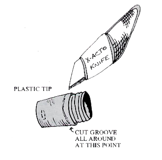
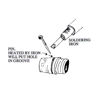
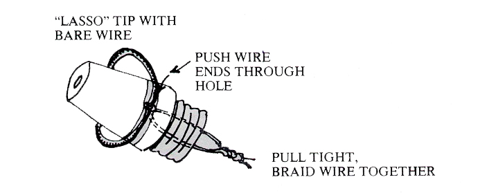
Figure 7 indicates the manner of construction of the touch ring. Strip a five inch or so length of wire entirely. If it is stranded as opposed to solid wire, make sure that you have twisted it together thoroughly, or it will unravel while you are threading it into the pen tip. The wire will loop all the way around the pen tip, into the groove hole, and should be tightly twisted to itself on the inside.
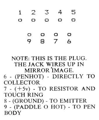
We are now ready to wire up the pen. Figure 8 provides a wiring diagram for connection to controller port 0. We shall be using the analog reading of Paddle (0) to tell us whether the touch ring is open or closed. The ground, pin 8, and the Paddle (0) hot lead, pin 9, form the touch ring circuit. As it turns out, this is an extremely convenient manner in which to activate and deactivate the pen. The resistor is connected between the collector and +5 volts, which is pin 7. The collector is also connected directly to pin 6, which is the hot pen lead. The emitter attaches to ground, which as stated, is pin 8 on the controller plug.
After the connectors have been soldered together with their respective leads, a test of the pen is in order, to make sure everything will be working when it is assembled. Plug the pen in, boot Atari Basic, and type the following:
|
|
| Figure 7. |
10 SETCOLOR 2,0,14:SETCOLOR 1,0,0:? PEEK(564),PEEK(565),PADDLE(0):GOTO 10
Upon running the program, hold the phototransistor up to different points on the screen, and ascertain that you are getting different readings for each position. Don't worry yet whether the readings are perfectly reasonable. Just make sure they change when the pen position changes. If they don't, you probably made a wiring mistake somewhere.
|
|
| Figure 8. |
When you touch the leads coming from pins 8 and 9 together, the last value printed in the program loop should move well down from its default, 228. If you are getting different PEEK values and paddle values, all is well, and you are in the home stretch.
Using the insulating tape, wrap up the pen wiring assembly so that nothing will short out when it is squeezed into the pen barrel. There is plenty of room in the pen for the assembly, so you shouldn't have to force anything.
Next solder two four- or five-inch insulated leads to connectors 8 and 9, which will detect our touch ring. One of these leads will connect directly to the tail of the touch ring, and the other will ground to the exterior barrel of the pen. This is easily effected by wrapping a generous length of stripped lead through the square hole in the plastic tip, as indicated in Figure 9. Then, when the plastic tip is screwed on, a good ground connection will be made via friction fit.
It is imperative that the connection to the touch ring itself be well insulated--your electrical tape will come in handy again here. Make sure no bare wire is left to accidentally short the switch. That way it will only close when your finger shorts it.
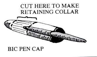
We're almost done. Bet you have been wondering what our Bic pen top is for. Well, now we need it. Cut off the tip and the bottom with the X-acto knife, as shown in Figure 10, so just about a half inch from near the top is left. This remaining collar will act as a guide for the phototransistor in the pen tip. Press it into the plastic tip, tapered side first, as shown.
After making a final inspection to ensure all bare wire has been insulated, push the wiring assembly into the barrel of the pen, leaving just the phototransistor peeking out about a half inch, and of course the switch leads and tip. Carefully screw on the tip, making sure that the phototransistor is seated well in the pen collar, and that a satisfactory ground connection is being made between the lead looped outside the plastic cap and the barrel of the pen. And that's it.
|
|
| Figure 9. |

Conduct another test, identical to the earlier one. If results are unsatisfactory, you'll have to undo things and find out where you went wrong. If you are having trouble activating the touch ring, try wetting your finger before you dismantle anything. Because we are reading the resistance between the ring and the barrel of the pen, a dry finger can sometimes be the culprit.
You should now have a relatively neat looking as well as functional light pen, that passes the one-line software test with flying colors. The time has come to begin refining that software dramatically.
I will provide two starting points. Figure 11 is a drawing program, which will give you an idea of how good (or bad) the pen is at locating itself. I built three pens, and the calibration seemed pretty consistent among them. Of course your monitor will have much to do with pen calibration.
The first place to look is line 70. Values in this line should be altered until the plot occurs right underneath the pen tip. If the left side of the screen reads okay but the right half is out, you may have to fiddle with the value in line 50. Don't get nervous. For most folks, the values shown in the program will be pretty close to perfect.
|
|
| Figure 10. |
You will quickly see that the pen is much more accurate at vertical measurement than at horizontal. This is probably its biggest shortcoming, though it has others. For one, the screen must be extremely bright to get a good reading. For this reason I have included an option to reverse color, which is chosen by pointing the pen to the text window and touching the ring. To erase, move the pen below the bottom edge of the text window.
Figure 12 is a simple menu selection program to give you an idea of the convenience of a light pen for varied information input. The pen you have built is more than accurate enough to support a function such as this. The squares in the listing are obtained by pressing the Atari key, followed by a space.
Needless to say, these examples are presented just to get you started. Your imagination can take it from here. So there you have it. You need never be stymied again when people ask you about the light pen capabilities of the Atari machine. In fact, they may be sorry they asked!
|
There are some hardware 800 models which cause the light pen to be read from port 4 on the 400. If you have a 400, plug the pen into port 4 and substitute PADDLE(6) for all references to PADDLE(0) in the demo programs. |
10 GRAPHICS 7:SETCOLOR 1,0,0:SETCOLOR 2,12,14:SETCOLOR 4,0,14:COLOR 1
20 POKE 752,1:? "TO DRAW, TOUCH THE PEN TO THE SCREEN,"
30 ? "THEN TOUCH AND RELEASE THE RING."
40 IF PADDLE(0)=228 THEN 40
50 X=PEEK(564):IF X<50 THEN X=X+230
60 Y=PEEK(565)
70 X=(X-95):Y=(Y-14)
80 TRAP 50:IF PADDLE(0)<228 THEN PLOT X,Y
90 IF PADDLE(0)<228 THEN 90
100 ? :? :? "TOUCH THIS BAR TO REVERSE COLOR, AND"
110 ? "BELOW THIS BAR TO ERASE."
120 X=PEEK(564):IF X<50 THEN X=X+230
130 Y=PEEK(565)
140 X=(X-95):Y=(Y-14)
141 IF Y>96 THEN 10
142 IF Y>83 AND Y<96 THEN 300
150 TRAP 120:IF PADDLE(0)<228 THEN DRAWTO X,Y
160 IF PADDLE(0)<228 THEN 160
170 GOTO 120
300 Y=0:SETCOLOR 4,0,0:? :? :? "TOUCH THE RING TO CONTINUE..."
310 IF PADDLE(0)=228 THEN 310
320 X=51:Y=0:SETCOLOR 4,0,15:GOTO 20
Figure 11.
10 GRAPHICS 0:SETCOLOR 2,0,0:SETCOLOR 4,0,0
20 ? :? :? :? :? "Question 1."
30 ? :? "How many zweckas does it take to fill"
40 ? "a quackenbush?"
50 ? :? :?
60 ? "[]ONE"
70 ?
80 ? "[]TWELVE"
90 ?
100 ? "[]HUNDREDS AND HUNDREDS"
110 ?
120 ? "[]WHO CARES ABOUT QUACKENBUSHES?"
130 Y=PEEK(565)
140 POSITION 2,22:IF Y>60 AND Y<64 AND PADDLE(0)<228 THEN ? "You must have a tiny quackenbush! "
150 POSITION 2,22:IF Y>66 AND Y<70 AND PADDLE(0)<228 THEN ? "No, but there are in a dozen.       "
160 POSITION 2,22:IF Y>76 AND Y<80 AND PADDLE(0)<228 THEN ? "You bet it does, buddy.            "
170 POSITION 2,22:IF Y>82 AND Y<86 AND PADDLE(0)<228 THEN ? "That's the wrong attitude to have."
180 GOTO 130
Figure 12.
John Anderson is an associate editor for Creative Computing magazine.
Table of Contents
Previous Section: CompuServe
Next Section: Atari Silencer