GAMING FIGURES
Gaming figures are those figures drawn on a computer screen for playing games. They include such things as balls, tanks, chessmen, and so on. For example, in a PONG game the gaming figure is a ball that the computer makes bounce around on the screen. In a game of tank war the gaming figure is a tank that we can move on the screen with an external control called a “paddle” or “joystick.”
Unlike most low-cost graphics computers the Apple II (in hires) has a unique method for handling gaming figures called shape tables. But before we cover this unique approach to gaming figures let's see the alternative approach that uses the more mundane features of BASIC and is easier to understand.
Elementary Gaming Figures
The simplest approach to creating a gaming figure (for vector graphics displays, that is) involves the storing of “vector end points” for a figure, inside of DATA statements, reading them into an array, and then using the array elements in a HPLOT statement inside a FOR…NEXT loop.
The actual technique for creating a vector end-point shape is as follows. First you get a piece of 0.1-inch (0.25-cm) grid paper (blue grid is best). Then draw the desired shape on the grid using lines and a “connect-the-dot” strategy, that is, outlining the shape with as few points as possible and then connecting these points with straight lines. Next you draw an imaginary X axis and Y axis through the middle of the shape. Then you read off the X and Y coordinates for each point, moving in a clockwise direction through the shape, while making a list. The values in the list are then placed in DATA statements in a BASIC program. The program reads the values into an array and then uses these values to draw the shape on the screen. Once we have the values for the end points of the shape in an array we can do all kinds of tricky things using the math functions of BASIC, including shrinking, translation, expanding, rotation, and so on.
Let's look at Example 15, showing how easy this is.
Example 16:
Draw a bird shape on 1/10-inch grid paper using a “connect-the-dot” strategy. Use as few dots as possible. Draw a vertical and horizontal axis through the middle of the shape; then make up a list of the X and Y values for each point on the shape.
Solution :
See Fig. 3-16.
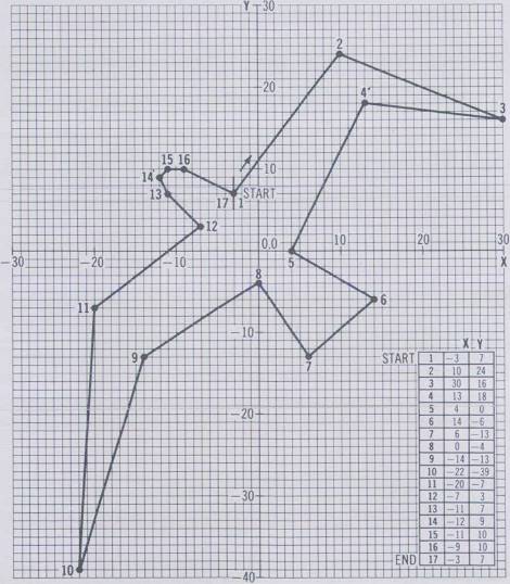
As you can see in Fig. 3–16 a list has been made of the coordinates of the X and Y points starting with point 1 at (-3, 7) and ending with point 17. Since the shape has only 17 points it won't take long to draw on the screen. The next step is to write a program to use the list of end points (Example 17).
Example 17:
Write a program for drawing the previous shape using the values in the list of Fig. 3–16. Store all the points in an array X(I) and Y(I) and then have the program draw lines between these points.
Solution:
10 HGR: HCOLOR = 3: F = 1.212 |
|
15 N = 16: DIM X(N), Y(N) |
←Dimensions arrays X(I) and Y(I) that will hold coordinates of gaming figure |
20 FOR 1 = 0 TO N: READ X(I): NEXT I |
|
25 FOR I = 0 TO N: READ Y(I): Y(I) = - Y(I)/F: NEXT I |
←Fill arrays from data statements |
30 HPLOT 140 + X(0), 80 + Y(0) |
|
35 FOR I = 1 TO N |
←Begin loop that draws the gaming figure |
40 HPLOT TO 140 + X(I), 80 + Y(I) |
|
45 NEXT I |
|
50 END |
|
10000 DATA - 3, 10, 30, 13, 4, 14, 6, 0, - 14, - 22, - 20, - 7, - 11, - 12, - 11, - 9, - 3 |
←Coordinates for gaming figure |
20000 DATA 7, 24, 16, 18, 0, -6, -13, -4, -13, -39, -7, 3, 7, 9, 10, 10, 7 |
See Fig. 3–17.
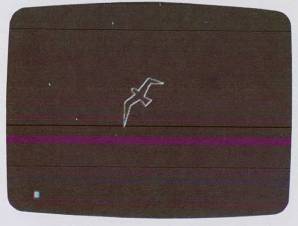
As you can see in Fig. 3–17, the bird shape is drawn almost exactly like it looks on the paper, except it is smaller. The program starts by switching into the high-resolution graphics mode in statement 10, then it sets N to equal the number of end points in the list minus 1 and DIMensions two arrays X(N) and Y(N). Next, in statement 20 we read in the elements of the X(I) array from the first DATA statement (statement 10000). Statement 25 is similar and reads in the Y(I) elements from DATA statement 20000. It also flips the Y(I) values upside down to compensate for the reversed Y axis of the Apple, and divides the Y(I) elements by F to compensate for the Y axis screen distortion.
In statement 30 we do an initial HPLOT using X(0) and Y(0) to get the first point on the screen. Next, in statement 35 we enter a FOR…NEXT loop that uses each element of X(I) and Y(I) in an HPLOT TO statement to draw the bird on the screen. Note the drawing loop starts with element 1 of each array because we used element 0 to define the starting point.
That is all there is to it, except, of course, the problem of moving the shape on the screen and changing its relative size. Let's look at both of these problems.
Moving the Shape
To move a shape which is defined by vector end points in an array we simply play with the values of the constants in the HPLOT TO statement that are added to the vector elements. Suppose, for example, we wanted the bird shape to appear to fly across the screen automatically. See Example 18, p. 127.
As you can see, the complexity of our program is growing, but the program becomes easier to understand. The first GOSUB 1000 statement causes the X and Y arrays to be filled with the information in the DATA statements. The variable P is used later to set the STEP size of a FOR…NEXT loop which controls the velocity of the movement (big steps make it move faster compared to small steps). The variable J is used to set the vertical position for the bird to a constant, such as 80 here.
At statement 40 we enter the main drawing loop, in which the variable I goes from 240 to 25 stepping by -15 to begin. We set the HCOLOR to white and then GOSUB to line 100, which causes the shape to be drawn out at location I, J on the screen.
Next, we change HCOLOR to black and erase the shape that is on the screen now. The loop is incremented and the process repeats until the shape reaches the left side of the screen, whereupon we make P larger and repeat the loop again. Since the step size is larger now the shape will appear to move faster.
That's all there is to it!
Shape Table Gaming Figures
Although the previous method for creating gaming figures (using floating-point arrays and DATA statements) is flexible and easy to visualize, it suffers from these problems:
- Speed—Floating-point BASIC array operations are just too slow for fast-acting animation. Therefore forget about using them for PONG games. They do work, however, for games where slow movement is permissible.
- No “Undraw”—There is no easy way to erase a shape without also erasing the drawing information underneath it. For example, if you have a green grid drawn on a black background and you draw a violet bird on the grid, when you erase the bird by drawing it in black you will wipe out a portion of the green grid.
- Hard to rotate, expand, etc.—Complex transformations often involving BASIC trig functions are required when you wish to rotate or expand a shape. These transformations are very slow and make fast-action animation impossible.
Anticipating that graphics users would want some powerful software for dealing with gaming figures, the designer of the Apple II cleverly incorporated the concept of shape tables in Applesoft, the floating-point BASIC.
A shape table is created by outlining a shape with tiny unit vectors which are all the same length but may be any one of four directions (up, down, left, right). The vectors are placed head to tail until the shape is outlined. Next, using a simple key, these direction vectors are converted to a string of bytes and then stored in memory as part of a shape table.
Example 18:
Change the previous bird drawing program to cause the bird to move from the right side to the screen to the left, so it looks like the bird is flying. Also, see if you can make the speed of the bird increase each time it sweeps across the screen. Two main tips are:
- Change the HPLOT TO 140 + X(I), 80 + Y(I) statement to HPLOT TO I + X(I), J + Y(I). The variable I controls the horizontal position and the variable J controls the vertical movement.
- Make the drawing part of the previous program a subroutine and make the main program a FOR…NEXT loop that increments the horizontal variable I, erases the old bird, and then draws the new bird in its new position.
Solution:
10 HGR: HCOLOR = 3 : F = 1.212 |
|
20 GOSUB 1000 |
←Fill array subroutine |
30 P = 15: J = 80 |
←P is the velocity, J the vertical position |
40 FOR I = 240 TO 25 STEP -P |
←Main draw and erase loop Draw it |
45 HCOLOR = 3:GOSUB 100 |
|
50 FOR D = 1 TO 50: NEXT D |
|
55 HCOLOR = 0: GOSUB 100 |
←Erase it |
60 NEXT I |
|
65 P = P + 2 |
←Increase velocity |
70 GOTO 40 |
|
100 HPLOT I + X(0), J + Y(0): FOR K = 1 TO N: HPLOT TO I + X(K), J + Y(K): NEXT K: RETURN |
←Draw gaming figure subroutine |
1000 N = 16: DIM X(N), Y(N) |
←Subroutine to fill gaming figure array with coordinates |
1010 FOR I = 0 TO N: READ X(I): NEXT I: FOR 1 = 0 TO N: READ X(I): Y(I) = -Y(I)/F: NEXT I: RETURN |
|
10000 DATA -3, 10, 30, 13, 4, 14, 6, 09, -14, -22. -20, -7, -11, -12, -11, -9, -3 |
|
20000 DATA 7, 24, 16, 18, 0, -6, -13, -4, -13, -39, -7, 3, 7, 9, 10, 10, 7 |
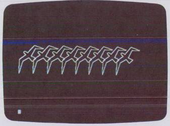
See Fig. 3-18.
You can store up to 255 shapes in a single table in memory. Once you have the object represented in a shape table you can get BASIC to draw it anywhere on the screen with the statement:
DRAW 1 AT X, Y
and you can erase the shape without erasing what is underneath it (nondestructive erase) with the statement:
XDRAW 1 AT X, Y
Here the 1 represents shape number 1 in the shape table and X, Y is any location on the screen.
Now the really great thing about these shapes is that you can have BASIC rotate the shape through 360° with the statement:
ROT = 0-64
The value after ROT sets one of 64 angles for the shape to be in when DRAW is used.
You can change the size of the shape from very small to larger than the screen with the statement:
SCALE = 1-255
The value after SCALE selects a size for all the unit vectors between 1 and 255. With SCALE you can make your shape expand or shrink on the screen in less than an eyeblink.
After you have constructed a shape with the vectors and the key conversion, you can save it permanently on cassette tape and then read it back into your BASIC program with the statement:
SHLOAD
which stands for SHape LOAD. Actually SHLOAD loads an entire shape table with up to 255 shapes in it.
Making a Shape Using a Shape Table
The actual procedure for creating a shape for a shape table is fairly simple but rather time-consuming. For this reason we will only cover the construction of a very simple shape with few vectors. We will, however, use more complex shapes in some later demonstrations in the book. See Example 19.
Example 19:
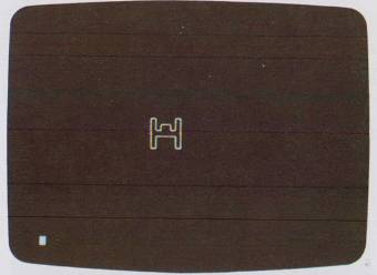
Show the steps for creating a shape table for a simple gaming figure, such as a Star Wars Tie Fighter™.
Solution:
The seven steps to creating a gaming figure for a shape table are design the shape out of vectors, unwrap the vectors, convert the unwrapped vectors to a table of hex bytes, add a header to the table, load the table into memory, save the table on tape, and finally load the table on tape into a BASIC program. Here is the complete procedure for a simple Tie Fighter gaming figure.
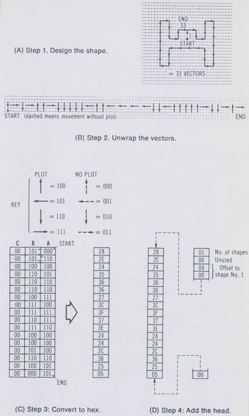
Step 1. Design the Shape
In Fig. 3-19A 0.1-inch (0.25-cm) grid paper was used to draw the outline of the gaming figure. To make the image on the screen look like the picture we draw on paper, we make the vertical vectors 0.4 inch (1 cm) and the horizontal vectors 0.3 inch or 0.76 cm (this makes the vertical vectors 25 percent longer than the horizontal vectors). The first vector starts at the approximate center of the shape so that when the shape is rotated the first vector spins about its center. The first vector is shown dashed to indicate that it is a move without actually plotting, i.e., we move but there is no vector drawn on the screen. Follow the vectors around the shape clockwise. The shape has 33 vectors when it is completed.
Step 2. Unwrap the Vectors
Unwrap the vectors left to right, starting with vector 1 (see Fig. 3-19B).
Step 3. Convert Vectors to Hex
Using the key shown in Fig. 3-19C, convert the vectors into a table of binary bytes and then convert these to hex values. Note the way the vectors are entered into the table. Section A is filled first, then B, then C, and then we move to section A of the next byte, i.e., the vectors are stored in right-to-left format.
Step 4. Add the Header
Since up to 255 shapes can be placed in a single shape table a header must be added to indicate how many shapes are stored and where the first shape begins. In the Apple this header indicates there is one shape and it starts four bytes from the table beginning. (See Fig. 3–19D.) We also must add a zero byte to the end of the shape to indicate the end of the shape.
Step 5. Load the Table into Memory
- Find the total table length. Here it is 22 bytes. Convert this to hex. Here this is hex 16. Load this number into memory locations 00 and 01 from the monitor
- Load the table into memory from the monitor using a memory area that is temporarily free and won't be clobbered from BASIC easily. If your table is less than 255 bytes use locations 300 to 3FF in the Apple. If your table is really long then you can set aside a high area of memory that BASIC won't touch for the table. But if you have a 16K machine you must make the table be below 8192. The author uses locations 1D00 to 1FFF and sets HIMEM to 7424. This frees 768 bytes for shapes, which is about 1400–2100 vectors. Enter the table (from Fig. 3-19D) using the Apple monitor.
* 0:16 00
* 1D00:01 00 04 .......... 25 05 00
Step 6. Store the Table on Tape
Save the current table in memory to cassette tape so it can be later called up with SHLOAD. Use the monitor to write the table like this:
* 0.1W 1D00.1D16W
The 0.1W writes the standard Apple header to the tape (table length in two bytes). The 1D00.1D16W writes the actual shape table data on the tape.
You should understand that at this point the shape will be saved on tape, and when SHLOAD is used next to load the table we can forget about where it is and how long it is.
Step 7. Load the Shape into Basic
To load the shape table stored on tape into a BASIC program we get into BASIC, start the recorder at the beginning of the table, and type:
SHLOAD
(You may also need to type HIMEM :8192 if you have a 16K Apple.)
Now we are ready to use our gaming figure with BASIC. What we need are some demonstration programs that illustrate the power of the shape table statements.
Paddle Control of Shape Position
One of the most interesting uses of gaming figures is in games where joysticks or paddles are used to move the shape about on the screen. High-resolution shapes are made for this, as we will see in the next program example (Example 20, p. 133).
The program starts out by switching into the graphics mode and setting the HCOLOR to white. Next we set the SCALE to be 5 and the ROTation to 0.
In line 100 we measure paddle PDL(0) to get a value between 0 and 255 for the X position. On the same line we measure paddle PDL(1) and divide it by 1.6 to get a value between 0 and 159 for the Y position. Recall that we have already loaded the shape with SHLOAD and it is sitting in memory waiting to be drawn on the screen.
Example 20:
Assuming the previous shape or one like it has been loaded into memory with SHLOAD, design a program that allows you to move the shape table gaming figure anywhere on the screen using a paddle or a joystick. Use the DRAW statements and set the SCALE to 5 and the ROTation to 0.
Solution:
5 MAX = 25 |
←Sets length of draw delay time |
10 HGR: HCOLOR = 3 |
|
20 ROT = 0: SCALE = 5 |
|
100 X = PDL(0) : Y = PDL(1)/1.6 |
←Read the paddle positions |
110 DRAW 1 AT X, Y |
←Draw the shape |
120 FOR I = 1 TO MAX: NEXT I |
←Delay for an instant |
130 XDRAW 1 AT X, Y |
←Un-draw the shape |
140 GOTO 100 |
←Repeat entire process |
See Fig. 3-20.
Statement 110 draws the shape in the table on the screen at position X, Y. Then a delay occurs by the FOR…NEXT loop in statement 120. This is necessary because the DRAW and XDRAW statements are so fast that flickering will occur unless we hold the shape on the screen for a brief fraction of a second.
Finally, in statement 130 we undraw and erase the shape with XDRAW, and in statement 140 we GOTO line 100 to repeat this draw and undraw process as a loop.
This program clearly demonstrates how easy it is to shuttle shapes across the screen. They move fast and smoothly. There are none of the problems of lag.
Paddle Control of SCALE and ROTation
Now to see how the SCALE and ROT statements work we can fix the X, Y position and use the paddles to control the scale and rotation. See Example 21.
Example 21:
Add to the previous program so that we can control the SCALE and the ROTation with the two paddles or a joystick.
Solution:
200 HGR: HCOLOR = 3 |
|
205 X = 140: Y = 80: MAX = 25 |
←Fix the X, Y position |
210 ROT = PDL(0)/4: SCALE = PDL(1)/8 + 1 |
←Set rotation and scale according to paddles or joystick |
220 DRAW 1 AT X, Y |
|
230 FOR I = 1 TO MAX: NEXT I |
|
240 XDRAW 1 AT X, Y |
|
250 GOTO 200 |
See Fig.3-21.
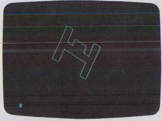
The most important thing in the program is to restrict the range of ROT to 0 to 64 (see line 210). The range of SCALE is kept between 1 and 64 to keep the shape from being larger than the screen (which would cause the shape to wrap around the screen).
Black Shapes on White Backgrounds
To make a simple change in the program that has a major effect on the display try reversing the color of the shape from white to black. See Example 22.
Example 22:
Show the simple but slow brute-force approach to generating a white background, and for contrast the fast slick CALL subroutine for changing screen color in a flash.
Solution:
The slow way:
300 HGR: HCOLOR = 3

310 FOR Y = 0 TO 159

320 HPLOT 0,Y TO 279, Y

330 NEXT Y

340 HCOLOR = 0: GOTO 205
The fast way:
400 HGR: HCOLOR = 3: HPLOT 0,0: |
|
CALL 62454 |
←This is a neat machine language subroutine in Applesoft that fills screen with last HCOLOR |
410 HCOLOR = 0: GOTO 205 |
The second method uses a CALL statement to almost instantaneously switch the screen color. The color is the last HCOLOR executed in the program. An HPLOT statement must be executed before the CALL statement is issued.
Return to Table of Contents | Previous Section | Next Section