GRAPHICS 8 In Four Colors Using Artifacts
David Diamond
A painless, no-POKE method for mastering Atari high resolution, four-color graphics from BASIC.
Contrary to what the Atari BASIC Reference Manualstates, GRAPHICS 8 is a true four-color mode (five colors if you count the border). Other articles have shown you how to obtain 16 or 128 colors by PEEKing, POKEing, and using machine language subroutines to fake out the operating system. This article is different. You can paint with four colors using simple, straightforward BASIC programming.
You probably have noticed that patterns drawn in GRAPHICS 8 often contain spurious colors. Atari sketches your television's resolution to its limits and the extra hues do sneak in.
The spurious colors seem random because they are appearing within a random pattern. They are, however, well-behaved. They can be harnessed, controlled, and used for brilliant displays.
Before I get into the details, try the following demonstration program:
10 GRAPHICS 8:COLOR 1
15 R=50
20 FOR X=-R TO R STEP 2
30 Y=SQR(R*R-X*X):REM Formula for a circle
40 PLOT 100+X,100+Y:DRAWTO 100+X,100-Y:REM Circle #1
50 PLOT 151+X,100+Y:DRAWTO 151+X,100-Y:REM Circle #2
60 NEXT X:FOR I=1 TO 350:NEXT I
70 FOR C=0 TO 15
80 SETCOLOP 2,C,4:SETCOLOR 4,15-C,8
85 FOR I=1 TO 350:NEXT I
90 NEXT C
Surprise! You have five vivid, solid colors on the screen at the same time. Now let's take a look at that program:
Line 10--Straight GRAPHICS 8. Standard color defaults.
Line 15--"R" is the radius of a circle.
Line 30--This is the formula for a circle: X2 + Y2 = R2. ("R*R" is
a little faster than "R^2").
Line 40--This draws the first circle. It is vertically cross-hatched
to fill it in with a solid color.
Line 50--This draws the second circle. But why is it a different
color from the first circle?
Line 20--Ah, here begins the secret: "STEP 2". Before reading
further, change it to "STEP 1" and rerun the program.
Lines 40,50--Here is the second half of the secret: "100+X" is an even offset. "151+X" is an odd offset. Change both occurrences of "151" to "150" on line 50, and see what happens. (Remember to set line 20 back to "STEP 2".)
Lines 70-90--These lines show you the wide range of color combinations available. Of course, when you are varying the luminance level, there will be even more.
Alternating Colored Fields
Without any additional programming lines, the circles can easily be changed into beach balls with alternating bands of color. Make sure that line 20 says "STEP 2", and change lines 40 and 50 as follows:
40 PLOT 98+X,100+Y:DRAWTO 101+X,100-Y:REM Circle #1
50 PLOT 147+X,100+Y:DRAWTO 150+X,100-Y:REM Circle #2
Changing the slope of the cross-hatching by a single horizontal point will add or remove one band of color. Increment the DRAWTOs by one horizontal point, and see what happens:
40 PLOT 98+X,100+T:DRAWTO 102+X,100-Y:REM Circle #1
50 PLOT 147+X,100+Y:DRAWTO 151+X,100-Y:REM Circle #2
Although the quirk that provides us with the extra colors seems somewhat magical, the reason for the varied solid colors is not. Remember that the "colored-in" areas are really comprised of finely separated, vertical lines. To better see what is happening, spread those lines out into a large grid for easier inspection:
10 GRAPHICS 8:COLOR 1
20 FOR X=10 TO 160 STEP 15
30 PLOT X,1:DRAWTO X,160
40 PLOT 1,X:DRAWTO 160,X
50 NEXT X
This isolates your three colors. The even column vertical lines are one color. Odd column vertical lines are a second color. Horizontal lines are the third color. (The background is the fourth, and the border is the fifth.)
Line 20 controls the colors. Try "FOR X = 10 TO 160 STEP 14" and try "FOR X = 9 TO 160 STEP 14".
When two adjacent lines touch each other ("FOR X =...STEP 1"), the two colors blend into the official color for graphics mode 8. Another way to look at it is that there are no longer separate lines when they touch, but rather a solid field of pixels.
The Alternating Color Phenomenon
The beach ball display, with its alternating bands of color, takes advantage of the fact that, with a pixel matrix, one cannot draw nearly vertical pure diagonal lines. Instead a series of shorter vertical lines are drawn, as shown below:
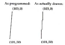
You can see that the three vertical line segments are drawn on odd, even, and odd columns, respectively, thus alternating colors.
Why Multiple Colors
The horizontal resolution limit of a television set is about 160 unique points. This is because on any one line of the television tube surface there are 160 sets of phosphor points which emit light when struck by the scanning electron beam. Each set actually contains three separate phosphor points--one that glows blue when struck, one that glows green, and one that glows red. Combinations of these dots in various intensities create the myriad of colors available.
Atari, in order to provide finer resolutions than 160 bytes across, plots 320 points across the screen--two for each set of color dots. (This is referred to as a half color cycle,or a half color clock.) Thus, even-column points will turn on the left portion of the three color phosphors, and odd-column points will turn on the right portion, producing alternating colors. The effect is referred to as artifacting.
Diagonal lines
Diagonal lines, ranging from vertical to almost 45 degrees, contain vertical components, and are therefore subject to the artifacting effects described above. However, when these lines are drawn on top of a ". . . STEP 2" solid colored field (such as demonstrated in the above programs), much of the spurious color effect is minimized, so that the "official" color for graphics mode 8 will be seen. If the background is dark, a medium intensity line will appear light (whitish). If the background is bright, a medium intensity line will appear dark (often a rich chocolate brown).
The bold splashes of multiple solid colored shapes can thus be combined with the more delicate effects of intersecting diagonal lines, as in the following demonstration program:
10 GRAPHICS 8: COLOR 1
20 SETCOLOR 4,15,10:SETCOLOR 2,0,15
30 FOR A=20 TO 140 STEP 2
40 IF A=100 THEN A=101
50 PLOT 65,20:DRAWTO A,1:DRAWTO A,A:DRAWTO A+30,70
60 DRAWTO 65,A:DRAWTO 30,A+40:DRAWTO 65,20
70 NEXT A
80 FOR I=1 TO 350:NEXT I
90 FOR COLOR=0 TO 15
100 SETCOLOR 2,COLOR,5:5ETCOLOR 4,15-COLOR,10
110 FOR I=1 TO 350:NEXT I
120 NEXT COLOR
Moire Patterns
No discussion of multiple colors would be complete without mentioning color moire patterns. There are two types of moire patterns. One type is the secondary pattern produced by the intersection of diagonal lines, such as is illustrated by demonstration Program 2, above. This type is not dependent on color for its effect. The second type is the subtle and delicate designs produced by shifts in color along diagonal lines. This type is dependent on the artifacting effect and is illustrated in the following program:
10 GRAPHICS 8: COLOR 1
20 FOR A=0 TO 319 STEP 3
30 PLOT 0,159:DRAWTO A,0
40 PLOT 319,0:DRAWTO 319-A,159
50 NEXT A
Notice that the pattern is whitest in the center, where the lines are not as steeply sloped, and also toward the upper right and lower left corners, where the lines are closest together. In addition to the white and the two artifacted colors, you may notice a fourth and fifth color along the top and bottom sections of the pattern. These extra colors are formed by a visualblending of the two artifacted colors. It is caused by the fact that the alternating colored areas are so close together that the eye has difficulty resolving them (a trick used by the Impressionists).
You can combine the various effects discussed in this article. Experiment with different color and intensity combinations. Blend in some dynamic color changes. You have a palette that any artist would envy.
Return to Table of Contents | Previous Section | Next Section