Chapter Three
Inside the 6502
In this chapter we're going to get under the hood of your Atari computer and see how it works. Then you'll be able to find your way around inside your computer and at last start doing some assembly language programming. As we explained in Chapter 1, every computer has three main parts: a Central Processing Unit (CPU), memory (divided into RAM and ROM), and input and output devices (such as keyboards, video monitors, cassette recorders, and disk drives). In a microcomputer, all of the functions of a CPU are contained in a microprocessor unit (sometimes abbreviated MPU). Your Atari's MPU is a 6502 microprocessor.
The Atari 6502 Microprocessor
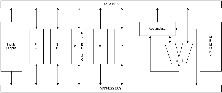
The 6502 microprocessor contains seven main parts: an Arithmetic Logical Unit (ALU) and six addressable registers. Data is moved around in side the 6502 chip and between the 6502 and other components in your computer over transmission lines called buses. There are two kinds of buses in an Atari computer: an 8-bit data bus and a 16-bit address bus. The data bus is used for passing 8-bit data and instruction bytes from one 6502 register to another, and also for passing data and instructions back and forth between the 6502 and your computer's memory. The address bus is used to keep track of your computer's 16-bit memory addresses: the addresses that instructions and data are coming from, and the addresses that instructions and data are being sent to.
The Arithmetic Logic Unit
The most important component in your computer is the 6502 chip. And the most important part of the 6502 chip is it's Arithmetic Logical Unit (ALU). Every time your computer performs a calculation or a logical operation, the ALU is where all of the work is done. The ALU can actually perform only two kinds of calculations: addition operations and subtraction operations. Division and multiplication problems can also be solved by the ALU, but only in the form of sequences of addition and subtraction operations. The ALU can also compare values, by subtracting one value from the other, and then noting the results of the subtraction operation. The 6502 chip's ALU has two inputs and one output. When two numbers are to be added, subtracted or compared, one of the numbers is fed into the ALU through one of its inputs, and the other number is fed in through the other input. The ALU then carries out the requested calculation, and puts the answer on a data bus so that it can be transported to wherever it's needed in the program.
In diagrams of the 6502 chip, the ALU is often represented as a V-shaped hopper. The arms of the V are the ALU's inputs, and the bottom of the V is the ALU's output. When a calculation or a logical operation is to be carried out by the ALU, one piece of data and an operand (an addition or a subtraction) instruction are deposited into one of the ALU's inputs (one arm of the V). The other piece of data is deposited into the input (the other arm of the V). When the calculation has been performed, its result is ejected through the ALU's output (the bottom of the V).
The Accumulator
The ALU never works alone; it carries out all of its operations with the help of a 6502 register called the accumulator (abbreviated "A"). When the ALU is called upon to add or subtract two numbers, one of the numbers is put on a data bus and then sent to one of the ALU's inputs, along with an operand. The other number is in the accumulator. When the bus carrying a number and an operand to the ALU discharges its cargo into the ALU, the accumulator puts the number it is holding on the data bus and sends that number to the ALU. When the ALU has carried out the requested calculation, it deposits the result of the calculation in the accumulator.
An Example
Suppose, for example, that you wanted your computer to add 2 and 2, and then place the result of its calculation into a certain memory location. You could use an assembly language routine like this one:
LDA #02
ADC #02
STA $CB
The first instruction in this routine, "LDA," means "LoaD the Accumulator" (with the value that follows). In this case, that value is 2. The "#" sign in front of the 2 means that the 2 is to be interpreted as a literal number, not as the address of a memory location in your computer.
The second instruction in the routine, ADC, means "Add with Carry." In this addition problem there is no number to be carried, the "carry" part of the instruction has no effect here, and all the ADC instruction does is add 2 and 2.
The third and last instruction in our routine, STA, means "Store the contents of the Accumulator" (in the memory address that follows).
As you can see, the memory address that follows the instruction STA is $CB, the hexadecimal equivalent of the decimal number 203. Since there is no "#" sign in front of the hex number $CB, your assembler will not interpret $CB as a literal number. Instead, $CB will be interpreted as a memory address, which is what a number has to be in assembly language if it is not a literal number. (Incidentally, if you did want your assembler to interpret $CB as a literal number, you would have to write it "#$CB." When a "#" symbol and a dollar sign both appear before a number it is interpreted as a literal hexadecimal number.) If the third line of our sample routine read STA #$CB, however, that would be a syntax error. That's because STA (store the contents of the accumulator in...) is an intruction that has to be followed by a value that can be interpreted as a memory address, not by a literal number.
Five Other Registers
Besides the accumulator, the 6502 processor has five other registers. They are the X Register, the Y Register, the Program Counter, the Stack Point, and the Processor Status Register. Here is a brief summation of the functions of each of these registers.
The 6502's Other Registers
- The X Register (abbreviated "X") is an 8-bit register that is often used for temporary storage of data during a program. But the X register has a special feature, too; it can be incremented and decremented with a pair of one-byte assembly language instructions (INX and DEX), and it is therefore often used as an index register, or counter, during loops and read/data-type instructions in programs.
- The Y Register (abbreviated "Y") is also an 8-bit register, and can also be incremented and decremented with a pair of one-byte instructions (INY and DEY). So the Y register, like the X register, is used both for data storage and as a counter.
- The Program Counter (abbreviated "PC") is a pair of 8-bit registers that are used together as one 16-bit register. The two 8-bit registers that are combined to make up the Program Counter are sometimes referred to as "Program Counter-Low (PCL)" and "Program Counter-High (PCH)". The program counter always contains the 16-bit memory address of the next instruction to be executed by the 6502 processor. When that instruction has been carried out, the address of the next instruction is loaded into the program counter.
- The Stack Pointer (abbreviated "S" or "SP") is an 8-bit register that always contains the address of the top element in a block of RAM called the hardware stack. The hardware stack, usually referred to simply as "the stack," is a special segment of memory in which data is often stored temporarily during the execution of a program. We'll go into more detail about how the stack works later on.
- The Processor Status Register (usually called simply the "status register," but abbreviated "P") is an 8-bit register that keeps track of the results of operations that have been performed by the 6502 processor.
The Processor Status Register
The Processor Status Register (P) is a little different from the other registers in the 6502 microprocessor. It isn't used for storing ordinary 8-bit numbers, as the 6502's other registers are. Instead, this register's bits are flags that keep track of several kinds of important information.
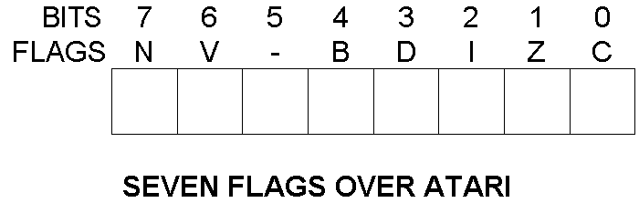
Four of the status register's bits are called status flags. They are the carry flag (C), the overflow flag (V), the negative flag (N), and the zero flag (Z). These four flags are used to keep track of the results of operations being carried out by the other registers inside the 6502 processor. Three of the P register's other bits, called condition flags, are used to determine whether certain conditions exist in a program. These three bits are the interrupt disable flag (I), the break flag (B), and the decimal mode flag (D). The eighth bit in the status register is not used.

Layout of the Processor Status Register
The status register can be visualized as a rectangular box containing six square compartments. Each "compartment" in the box is actually a bit, and each bit is used as a flag.
If a given bit is a "1" instead of a "0," then it is said to be a flag that is set.
If a given bit is a "0" instead of a "1," then it is said to be a flag that is cleared.
The bits in the 6502 status register, like the bits in all 8-bit registers, are customarily numbered from 0 to 7. The rightmost bit is bit 0. The leftmost bit is bit 7.
An Illustration of the Processor Status Register
Here's a complete list of the flags in the 6502's processor status register, and an explanation of what each one means.
Bit 0 (The Rightmost Bit)
The Carry Flag (C)
As we saw in Chapter 2, it isn't easy to do 16-bit arithmetic with an 8-bit chip like the 6502. When the 6502 chip is required to perform an addition operation on a number greater than 255, or if the result of a calculation might be greater than 255, a program has to be written that will break each number down into 8-bit segments for processing, and will then patch all of the numbers back together again. This kind of mathematical cutting and pasting, as you can probably imagine, involves a lot of carrying (if addition problems are being performed) and borrowing (when the 6502 is performing subtraction). The carry flag of the 6502 P register is the flag that keeps up with all of this carrying and borrowing.
If an addition operation results in a carry, the carry flag is automatically set. And if a subtraction operation requires a borrow, the carry flag keeps track of that too. Since the carry flag is almost constantly being set and cleared as a result of carries and borrows in addition and subtraction, it's always a good idea to clear it before an addition operation is to be carried out, and to set it before a subtraction operation takes place. Otherwise, there's a chance that your calculation will be messed up by the leftover results of previous addition and subtraction operations.
In addition to keeping track of carrying and borrowing operations, the P register's carry flag is also used in operations involving comparisons of values, and in certain shift and rotate operations to check, compare and manipulate specific bits in binary number. We'll discuss number comparisons and bit operations in later chapters. For now, it's more important to remember that the assembly language instruction to clear the P register's carry bit is CLC, which stands for Clear Carry," and that the instruction io set the carry bit is SEC, which stands for "SEt Carry."
Bit 1 (The Second Bit from the Right)
The Zero Flag (Z)
When the result of an arithmetical or logical operation is zero, the status register's zero flag is automatically set. Addition, subtraction and logical operations can all result in changes in the status of the zero flag. If a memory location or an index register is decremented to zero, that will also result in a set zero flag. An ironic 6502 convention is that when the result of an operation is zero, the zero flag is set to 1, and that when the result of an operation is not zero, the zero flag is cleared to 0. It's important to understand this concept, since it would be easy to assume that the zero flag operates in just the opposite manner. There are no assembly language instructions to clear or set the zero flag. It's strictly a "read" bit, so instructions to write to it are not provided.
Bit 2 (The Third Bit from the Right)
The Interrupt Disable Flag (I)
Some Atari programs contain interrupts; instructions that halt operations temporarily so that other operations can take place. Some interrupts are called maskable interrupts because you can prevent them from taking place by including "masking" instructions in a program. Other are called nonmaskable because you can't stop them from taking place, no matter what you do. When you want to disable a maskable interrupt, you can do it with the P register's interrupt disable flag. When the flag is set, maskable interrupts are not permitted. When it is clear, they are allowed. The assembly language instruction to clear the interrupt flag is CLI. The instruction to set the interrupt flag is SEI.
Bit 3 (The Fourth Bit from the Right)
The Decimal Mode Flag (D)
The 6502 processor normally operates in binary mode, using standard binary numbers of the type that were discussed in Chapter 2. But the 6502 can also operate in what is known as a binary coded decimal, or BCD mode. To put the 6502 into BCD mode, you have to set the decimal flag of the 6502 status register. BCD arithmetic is slower than plain binary arithmetic, and it also consumes more memory. But its results, unlike those of plain binary arithmetic, are always s 100 percent accurate. Therefore it is often used in programs and routines in which accuracy is more important than speed or memory efficiency.
One example of a program that uses BCD arithmetic is your Atari BASIC interpreter. In Atari BASIC all numbers are stored as 6-byte BCD number, and all arithmetic is performed as BCD arithmetic. Because of this feature, Atari BASIC runs somewhat slowly. But its calculations yield accurate results. Another advantage of BCD numbers is that they're easier to convert into decimal numbers than plain binary numbers are. So BCD numbers are sometimes used in programs that call for the instant display of numbers on a video monitor as well.
We'll discuss BCD at grater length in Chapter 10, Assembly Language Math. For now, it's sufficient to say that when the status register's decimal mode flag is set, the 6502 chip will perform all of its arithmetic using BCD numbers. BCD arithmetic is rarely what you want when you use an Atari computer, so you'll usually want to make sure that the decimal flag is clear when your computer is doing arithmetic. The assembly language instruction that clears the decimal flag is CLD. The instruction that sets the flag is SED.
Bit 4 (The Fifth Bit from the Right)
The Break Flag (B)
The break flag is set by a special assembly language instruction, BRK. Program designers often use the break instruction in assembly language programs during the debugging phase. When the instruction is used and the break flag is set, certain error-flagging operations take place and control of the computer returns to the programmer. The break instruction is a highly complex sophisticated debugging tool, and we won't go into much detail about it in this volume. But you can learn more about it in some of the advanced 6502 programming texts listed in the bibliography
Bit 5 (The Sixth Bit from the Right)
[Unused Bit]
For some reason, the microprogrammers who designed the 6502 status register left one bit unused. This is the one.
Bit 6 (The Second Bit from the Left)
The Overflow Flag (V)
The overflow flag is used to detect an overflow from bit 6 (the next to rightmost bit) in a binary number. If you don't know what that means yet, don't be concerned about it; the overflow flag used primarily in advanced 6502 arithmetic, specifically to keep track of changes in the plus and minus signs of signed number when signed binary arithmetic is being performed. As an Atari assembly language programmer, you�ll rarely, if ever, have a occasion to use the overflow flag. Nevertheless, we'll discuss it at greater length in Chapter 10, Assembly Language Math. For now, all we'll add (just for the record) is that the assembly language instruction that clears the overflow flag is CLV. There is no instruction to set the flag.
Bit 7 (The Leftmost Bit)
The Negative Flag
The negative flag is set when the result of an operation is negative, and cleared when the result of an operation is zero. It is often used in operations involving signed numbers, and it also has other uses that will be discussed in later chapters. There are no instructions to set or clear the negative flag. There is no need for any, since the flag is used for test purposes only.
Your Big Chance
Now that you know what goes on inside your computer's 6502 processor, you're ready to write, and run, your first assembly language program. You will have a chance to do just that in the next chapter. But first, here's a chance to run another bonus program containing some machine language values that can be POKEd inform a BASIC program. This routine, Bonus Program No.3, will turn your computer keyboard into a musical keyboard. Type it and run it, and then we'll take a look at how it works.
BONUS PROGRAM NO. 3
SOUNDOFF.BAS
10 REM "D:SOUNDOFF.BAS"
20 INKEY=35:FREQ=53760
30 SOUND 0,0,0,0:GRAPHICS 0:OPEN #1,4,0,"K:"
35 GET #1,K:IF K=32 THEN SOUND 0,0,0,0:PRINT CHR$(K):GOTO INKEY:REM 32 IS A SPACE
40 IF K>64 OR K>122 THEN GOTO INKEY:REM NOT A LETTER
50 IF K>90 AND K<97 THEN GOTO INKEY:REM NOT A LETTER
60 IF K>90 THEN K=K-32:REM CHANGE LOWER CASE TO UPPER CASE
70 TONE=K-64:IF TONE<1 OR TONE>7 THEN GOTO INKEY:REM NOT A,B,C,D,E,F OR G
80 PRINT CHR$(K);:GOSUB 1000
90 ON TONE GOTO 100,200,300,400,500,600,700
100 POKE FREQ,145:GOTO INKEY:REM A
200 POKE FREQ,134:GOTO INKEY:REM B
300 POKE FREQ,121:GOTO INKEY:REM C
400 POKE FREQ,108:GOTO INKEY:REM D
500 POKE FREQ,96:GOTO INKEY:REM E
600 POKE FREQ,91:GOTO INKEY:REM F
700 POKE FREQ,81:GOTO INKEY:REM G
1000 SOUND 0,255,10,8:RETURN :REM SET UP AUDIO REGISTERS TO PLAY NOTSLIST
Download (Saved BASIC)
Download / View (Listed BASIC)
How it Works
In lines 30 and 35 of this program the audio registers of your computer are cleared to zero and a loop is set up to print characters on your screen. In lines 40 through 70 some checks are carried out to see if any characters that have been typed are valid notes, A, B, C, D, E, F or G. If a character is typed in lower case, it is automatically converted to upper case in line 60 to make the program work smoother. In the subroutine at line 1000 the audio registers in your computer are reset to play the notes A through G when the corresponding letters are typed, unless the character is a space. If the character is a space, all audio registers are turned off, a space is printed on the screen, and the computer is instructed to wait for the next typed character (that happens in line 35).
The machine language instructions in the program are in lines 100 through 700. In those lines a certain memory register in your computer (called FREQ in this program) is stuffed with a value that equates to a musical note. Each time that value changes, the note being played changes accordingly. This is a very simple program that doesn't even begin to explore the complex sound capabilities of Atari computers. Still, the ways in which it can be expanded are limited only by the user's own imagination. By making the program a little more complicated, you could add the capability of reproducing sharps and flats (with the control key, for example), and you could also add more octaves (for instance with the shift key, the numbers keys, or shift/control key combinations). You could make the screen change colors as the notes change or you could save melodies in your computer's memory and save them on a disk and you might even be able to figure out a way to play chords! You could do all of those things in BASIC, if you wished or, if you were more ambitious, you could move beyond BASIC and continue to learn more about how to put your Atari through its paces using assembly language. Which brings us to Chapter 4. Read on.
Return to Table of Contents | Previous Chapter | Next Chapter
