Locations 0 to 255 are called "Page Zero" (in the language of computers, a "page" is 256 bytes). Since one byte can hold any number in the range of 0 to 255, the computer only needs one byte to hold the address of a page zero location. This saves time when you have to load or store a value in machine language, so page zero is very important to machine language programs that have to run as quickly as possible. That's why the operating system uses the first 128 bytes. The other 128, locations 128 through 255, can be used by BASIC and you for superfast machine code.
Machine language programmers should note that locations 2 through 7 are not cleared by either a cold start (turning the computer off and then on again) or warm start (pressing SYSTEM RESET) operation.
LINZBS
0,1 0000,0001
The great mystery location! Nobody seems to know exactly what this location does. According to Atari's operating system listing, it is "LINBUG RAM [and] will be replaced by [the] monitor RAM" (your guess is as good as mine), and the only time it uses it is to define it. It does seem to be used to store the VBLANK timer value though, so it's probably not completely useless.
CASINI
2,3 0002,0003
This is used in "cassette initialization." As you probably already know, if you hold down the START button while turning on the computer, the computer will beep. If you then press RETURN, the computer will expect a machine language tape to be in the cassette recorder and will proceed to load it. This process is called "booting" a cassette. The first six bytes stored on the machine language tape contain special information about the tape. The first byte, actually, is ignored. The second tells how many 128 byte "records" are on the tape (when you load in the tape, each beep while loading represents a record). The third and fourth give the starting address memory that the machine code is to be stored at, called the "load" address. The fifth and sixth give the "initialization" address (where to go to get the program set up and ready to run). The initialization address, as you may have guessed, gets stored here at CASINI. Once the whole program has loaded, the computer jumps to the load address plus six (to skip over these special bytes) where the program either tells it to load some more or RTS (ReTurn from Subroutine). When the computer comes across an RTS instruction, it looks in CASINI for the initialization address and JSRs (Jump to SubRoutine) to that address. Finally (and you thought cassette boots were easy), the computer JSRs to the address in DOSVEC (10,11), which gets the program running (DOSVEC should be set up by the program either in the initialization process or as part of a multiple load).
RAMLO
4,5 0004,0005
RAMLO has a bunch of uses, none of which will be useful to you. First, the OS uses it as an index (like the variable in a FOR/NEXT loop) while clearing out memory after you turn on the computer. It also uses it as an index while testing memory to make sure everything is A-OK. Finally, and you'll love this one, it's used to store the "disk boot address," which is usually 1798 in case you care, for the boot continuation routine (which is what happens when you want to load into more than one part of memory). By the way, it's real buddy-buddy with TRAMSZ and TSTDAT (the three work together in the RAM test routine).
TRAMSZ
6 0006
Another location with a whole bunch of uses. As mentioned, TRAMSZ helps out RAMLO in testing the RAM. Its value is then transferred to RAMTOP (location 106). But, before any of that happens, it is used in testing whether or not a left cartridge is plugged in. If there is a left cartridge (also known as cartridge A), then TRAMSZ is set to one. If not, it's set to zero.
TSTDAT
7 0007
This one only has two functions. First, as you already know, it helps out in the RAM test routine (see your OS listing if you're dying to find out what the RAM test routine is). Secondly, like TRAMSIZ, it's used initially in testing whether or not the right, or B, cartridge is present.
Machine language programmers: Locations 8 through 15 are cleared on cold start only.
WARMST
8 0008
This is the warm start flag, telling you whether you're in the middle of a warm start or a cold start. If WARMST equals 0, then you're in the middle of a cold start. If it's anything else, then you're in the middle of a warm start (pressing SYSTEM RESET will set WARMST to 255). The main purpose of WARMST is to make sure that if someone presses the SYSTEM RESET button before everything is initialized properly, the computer will know about it and start over instead of messing everything up. Nice stuff to know, but generally useless. But wait, you say, can't I trick the computer into rebooting by changing the value of WARMST to 0, that way preventing people from using SYSTEM RESET to stop my BASIC program so they can LIST it? No. Although you can change the value to 0, as soon as you press SYSTEM RESET it will change back to 255. See location COLDST (580) for a way that you can trick the computer. You might also look at locations POKMSK (16) and STMCUR (138,139) for other ways to protect your BASIC programs from other people's greedy eyes.
Incidentally, warm start normally starts at location 58484.
BOOT?
9 0009
Booting, as you will recall, is the process of loading the program into the computer's memory. In our case the program is loaded from tape or disk. Sometimes a boot is not successful. Maybe you put a rock and roll tape into your Atari recorder by mistake, or you forget to close the disk drive door. In any case, BOOT? is used to tell the operating system whether or not the boot attempt was successful. If BOOT? is equal to one, then there was a successful disk boot. A two indicates a tape boot, and a three (a one plus the two) means both the disk and tape booted. A zero means that everything bit the big one.
If a cassette boot attempt doesn't work, then the OS goes on as though there were no attempt. If the disk boot attempt fails, and this has happened to most of us, then a lovely "BOOT ERROR" message appears on the screen and the OS gives it another try.
OK, now for some miscellaneous stuff. A cassette boot always comes before a disk one. If there is a sucessful cassette boot, then every time SYSTEM RESET is pressed the computer will go to the address stored in CASINI.

The address is a location where a routine you want to use is located in memory. This address is usually called a VECTOR, because it points to something. You can JSR in machine language or USR in BASIC to get to the routine.
Back to CASINI. If the disk boots sucessfully, then the computer will go to the address stored in DOSVEC (10, 11). If BOOT? is set to 255 by you, then the computer will "lock up" if SYSTEM RESET is pressed. This is a great way to keep people from looking at your programs. Incidentally, "lock up" means that the computer will not do anything until you turn it off.
DOSVEC
10,11 000A, 000B
This is another vector, used to tell the OS what to do when SYSTEM RESET is pressed. It holds the cassette boot starting address, the disk boot starting address, or the address of the "black-board mode" routine (type `BYE' from BASIC and press RETURN; that's the blackboard mode and the routine for it starts at location 58481). It's called DOSVEC, because if you're using DOS from BASIC, DOSVEC holds the address that BASIC jumps to when you call DOS (DOS VECtor - get it?). If you want to use this location from BASIC to point to your own routine, then you'll have to make a small change to DOS, since in this case SYSTEM RESET restores DOSVEC to its original value. The change is easy to make, though. All you have to do is POKE 5446 with the Least Significant Byte (LSB) of the address of your routine, and 5447 with the Most Significant Byte (MSB) of the address. The MSB is the first two digits of the hex address, the LSB is the last two. You can compute MSB and LSB from a decimal address with the following formulas: MSB=INT(address/256), LSB=address-(256*MSB). Then call DOS and resave it using the WRITE DOS FILES option. This will give you a custom version of DOS that will allow your routine to run every time SYSTEM RESET is pressed or DOS is called.
Miscellaneous stuff again, DOSVEC is set to 6047, the address of a routine to load in the DUP.SYS file, if DOS is used and it is not told otherwise (i.e., no user boot programs). And, for you machine language dabblers, if you create an AUTORUN.SYS file that doesn't end with an RTS, make sure you set BOOT? to 1 and COLDST (580) to 0 (so as not to confuse the computer).
DOSINI
12,13 000C,000D
This one's easy. Essentially, it is the disk equivalent of CASINI. As a matter of fact, the cassette initialization address is stored here before the OS realizes it's doing a cassette boot and moves it to CASINI. If there is no cassette or disk boot, DOSINI will read 0, 0.
DOSINI can be very useful because it holds the address that the OS jumps to when SYSTEM RESET is pressed. If you have a machine language routine that you want to go to whenever SYSTEM RESET is pressed, store its address here.
APPMHI
14,15 000E,000F
This location helps prevent your programs from accidentally being written over by the OS. If you're using BASIC, it points to the end of your BASIC program. The OS uses it to determine whether or not there's room for the graphics mode you want to use. As you probably know, the graphics mode stuff (screen memory and display list) is stuck way up at the top of memory. When you tell the OS to set up a graphics mode (with either a GRAPHICS or OPEN "S:" command), it tries to put the display list and screen memory right below the top of memory. Unfortunately, sometimes there isn't enough room, and they would extend down into your program, which you obviously don't want to happen (unless it's a horrible program). APPMHI to the rescue! Before it sets up the requested graphics mode, the OS checks APPMHI to see if there's enough room. If there isn't, it tells you so and sets up a GRAPHICS 0 screen instead, updating MEMTOP (741,742) in the process. MEMTOP, in case you didn't guess, holds the address of the last possible memory location you can use for your program, i.e., the memory location right before the display list. On the other hand, if there is enough room, the desired mode will be set up and MEMTOP updated accordingly.
Sometimes you may want to use the memory between the end of your program and MEMTOP to store character sets, or player/missile information. That's fine, but make sure you change APPMHI so that the OS knows that you're using that memory (in other words, set APPMHI to point to the memory address after the last one you use). Other locations that might be of interest here are CHBASE (54281), PMBASE (54279), and RAMTOP (106).
Machine language programmers: Locations 16 through 127 are cleared on either cold start or warm start.
POKMSK
16 0010
POKMSK is used to turn various types of "interrupts" on or off. An interrupt is exactly what it sounds like; the computer gets interrupted from whatever it's doing and told to do something else (it then usually returns to what it was doing before it was so rudely interrupted).
For machine language programmers, POKMSK deals with POKEY interrupts and is used and altered by the IRQ service. It's also a shadow register for IRQEN (53774).
The following chart (Figure 3) shows exactly what part of POKMSK deals with which interrupts. Change a specific bit to a one to turn on that interrupt, zero to turn it off.
Before we decide whether or not any of this is useful, a few notes for the diehards. The default value for POKMSK is 192; BREAK key and "other key" interrupts enabled.
| BIT NO. |
DECIMAL VALUE |
|
TYPE
OF INTERRUPT |
| 6 |
64 |
"Other key" | |
| 5 |
32 |
Serial input data ready | |
| 4 |
16 |
Serial output data required | |
| 3 |
8 |
Serial out transmission finished | |
| 2 |
4 |
POKEY timer four ('B' and later OS ROMs only) | |
| 1 |
2 |
POKEY timer two | |
| 0 |
1 |
POKEY timer one |
FIGURE 3. POKMSK chart

When you enable a timer interrupt, the associated AUDF register will be used as a timer and will generate an interrupt request (IRQ) when it has counted down to zero. See VTIMR1/2/4 (528 to 533) and the POKEY chip (53760 to 54015) for more details.
For you beginners, as well as the pros, there is a handy-dandy use for for POKMSK. If you haven't guessed already it allows you to disable the BREAK key so that nobody can BREAK into your program and steal your code. All you have to do is turn bit seven off. How do you do that? Try the following subroutine:
1000 BK = PEEK(16):IF BK > 128 THEN POKE 16,BK -128:POKE 53774,BK -128
1010 RETURN
Notice that we also change location 53774. As mentioned before, POKMSK is a shadow register for 53774, and therefore both must be changed. We also check first to make sure that bit seven is on. We do this because, unfortunately, this routine has to be called more than once. You see, the BREAK key is re-enabled by the first PRINT statement that prints to the screen, by an OPEN "S:" or OPEN "E:" statement, by the first PRINT statement after such an OPEN, by the first PRINT statement after a GRAPHICS command, or by a SYSTEM RESET. Phew! To make sure you keep the BREAK key disabled, you'll want to GOSUB to the preceding routine after each such command.

More for the machine language programmer. If you have the newer OS 'B' ROM, there is a vector for the BREAK key interrupt that allows you to write your own routine for the BREAK key. It is called BRKKEY, and can be found at locations 566 and 567.
BRKKEY
17 0011
OK, you've used POKMSK to zonk out the BREAK key. What happens if for some reason you need to know if somebody's pressing it? BRKKEY tells you just that. If it's equal to zero then the BREAK key is pressed (if it's not then it isn't!). If you're looking at BRKKEY from BASIC, remember that you'll have to keep checking it over and over again; BRKKEY tells if BREAK is pressed, not if it were.
Machine language programmers, this location along with POKMSK lets you write your own BREAK key routines if you don't have the 'B' ROM, or if you want to make sure your software will work on the old ROMs. If you do have the 'B' ROM (location 58383 will equal zero if you do), you can use the vector mentioned under POKMSK.
A few boring bits of information. If the BREAK key is pressed during an input/output (I/O) operation, BRKKEY will read 128, not 0. The keyboard, display, screen, and cassette handlers all check BRKKEY to see if they should BREAK (why else?), as do I/O routines and scroll and draw routines. Also look at locations STATUS (48) and DSTAT (76) for related stuff.
RTCLOK
18-20 0012-0014
This one's actually fun and interesting, and you may even have used it already. It's a clock - the "internal realtime clock" (which just means that it's inside the machine and actually keeps good time). It doesn't count in seconds though, but rather "jiffies." A jiffy is a sixtieth of a second, which happens, not by coincidence, to be the time that it takes the television set to fill the screen. After the screen is filled, a special interrupt occurs, called the Vertical BLANK (VBLANK) interrupt. The OS gets a lot of things done during VBLANK, one of which is updating RTCLOK. Every jiffy (during VBLANK), location 20 gets increased by 1 until it equals 255. At that point, since 255 is the largest number a memory location can hold, it gets reset to 0 during the next VBLANK, and location 19 gets increased by 1. You can probably guess what happens next. When location 19 reaches 255, it gets set to 0 during the next VBLANK and location 18 gets increased by 1. Finally, when location 18 reaches 255, everything gets reset to 0 and the whole thing starts all over again. So, to put things in a more understandable perspective, location 20 increases by 1 every sixtieth of a second, location 19 every 4.27 seconds (256/60), and location 18 every 18.2 minutes (4.27 seconds*256).
The following routine will tell you the number of jiffies, seconds, and minutes that the clock has been running, i.e., since you turned on the computer or last POKEd 18 to 20 with zeros.
10 J = PEEK(20) + PEEK(19)*256 + PEEK(20)*256*256
20 S = J/60
30 M = S/60
40 PRINT "RTCLOK reads ";J;" jiffies, or ";S;" seconds, or ";M;" minutes."
All three locations are set to zero when you turn on the computer or press SYSTEM RESET. You can set them to whatever values you want just by POKEing them. Possible uses for RTCLOK include timing things that need precise timing. You can even use it to keep track of the time (what an absurd use for a clock).
BUFADR
21,22 0015,0016
This is a temporary register used to store the disk buffer address. It exists so that the OS can use indirect addressing to access the disk buffer. If this doesn't make sense, then BUFADR is not the place for you.
ICCOMT
23 0017
Another hardcore location. ICCOMT holds the CIO (Central Input Output) command and is used as an index into the command table to find the offset for the correct vector to the desired handler routine. Like I said, for hardcores only.
DSKFMS
24,25 0018,0019
This is used as a vector to the FMS (File Management System). It is called JMPTBL by DOS (which doesn't know any better).
DSKUTL
26,27 001A,001B
Another location used by DOS. DOS calls it BUFADR, but we'll continue to call it DSKUTL so as not to get confused with the OS BUFADR (21,22). DSKUTL points to a buffer that the disk utilities package (DUP) uses when copying or duplicating a file. If the user says it's OK to use the program area while copying or duplicating, then DSKUTL gets the value in MEMLO (743,744). If the user says no way to the program area, then DSKUTL gets the address of DBUF, a special 250-byte buffer at location 7668.
PTIMOT
28 001C
If you're not a big fan of machine language I/O, then skip this one. PTIMOT is the printer timeout value. It's set by your printer handler software, and initialized by the OS to 30, which represents 32 seconds. If you're good at math you'll realize that 60 would represent 64 seconds. It's updated after each printer status request, getting the specific timeout status from DVSTAT+2 (748).
A timeout is essentially what it sounds like. The printer (it could also be a disk drive or similar device) says, "Hey, timeout," and takes five. This has the noticeable effect of the printer just sitting there for a brief period of time doing nothing. Then it decides to come back and get to work again. What are you going to do, fire it? Anyway, those of you with the original OS may be very familiar with this situation, since that version of the OS contained a bug causing unnecessary timeouts. You would be doing something like printing when all of a sudden the computer would stop everything for up to five minutes. Version B did away with it.
PBPNT
29 001D
PBPNT is an index (pointer) into the print buffer. It tells the OS how full or empty the buffer is, and can therefore have any value from zero up to the size of the print buffer, PBUFSZ (30).
PBUFSZ
30 001E
PBUFSZ is the size of the print buffer, but not necessarily the size of the print line. The normal buffer size is 40 bytes (which is obviously not the normal line size for most printers). It is initialized to zero by the OS (and not set until P: is opened), and set to four in the case of a printer status request.
Characters get stored in the print buffer on their way to the printer. The OS checks PBPNT (29) to see whether it's equal to the buffer size (which would mean that the buffer is full) and, if it is, the buffer gets sent to the printer. If the buffer gets an EOL (End Of Line) character, then the OS fills the rest of the buffer with spaces and sends it to the printer.
PTEMP
31 001F
This is used by the printer handler to temporarily hold the character being sent to the printer while it goes off and does some chores.
PAGE ZERO INPUT/OUTPUT CONTROL BLOCK (ZIOCB)
The 16 locations from 32 to 47 are used by CIO to make I/O as efficient as possible (remember the speed advantage of page zero). They are set up the same way as the regular IOCBs (832 to 959) and essentially act as a mirror for the IOCB that wants to be used. In other words, when a CIO operation gets going, the information in the IOCB that's involved is moved to here, where it is used by the CIO routines. When the CIO is all done, then the updated information is moved back to the IOCB. Remember, as complicated as this sounds, it's only done for the sake of speed.
For more information on ZIOCB, CIO, and the rest of the I/O process, see the appendix on I/O.
ICHIDZ
32 0020
This serves as an index into the handler address table for the file that's currently open on this particular IOCB. If there is no such open file (i.e., the IOCB is free), then ICHIDZ gets set to 255.
ICDNOZ
33 0021
The device or drive number. DOS uses it to tell the maximum number of devices, and therefore calls it MAXDEV (I'll bet you can see a connection there). It gets initialized to one.
ICCOMZ
34 0022
This is the command byte, which is set by the user, in the course of setting up the regular IOCB, to tell CIO what kind of operation is to be performed (GET, PUT, FORMAT, etc.). It also determines the format of the rest of the IOCB (which will be different for different commands).
ICSTAZ
35 0023
ICSTAZ is the status of the last IOCB action taken. The device in question tells CIO what happened, CIO tells the OS, and the OS sets ICSTAZ (a little chain of command here). Hopefully everything went OK, but if it didn't, ICSTAZ is the guy who'll know.
ICBALZ,ICBAHZ
36,37 0024,0025
Another buffer address, this one for data transfer. The OS also uses the ICBAZ twins to get the device name from the user (in this case ICBALZ / HZ holds the address of the location where the device name has been stored).
ICPTLZ,ICPTHZ
38,39 0026,0027
Each device has its own routine to "put" a byte into the device. The OS sets this location to hold the address (minus one) of the routine for the device being used. When the file is CLOSEd (and on powerup), it is set to the address of CIO's error routine for an illegal put (because you can't put something into a device unless it's open).
ICBLLZ,ICBLHZ
40,41 0028,0029
More buffer stuff. This time we have a counter that is initially set to the maximum number of bytes to PUT or GET in an I/O operation. It gets decremented every time a byte is put or gotten.
Machine language programmers can set this location to the size of the memory block they want to transfer. By checking after each PUT/ GET to see if it's equal to zero, you'll be able to tell when the transfer is done.
ICAX1Z
42 002A
This is the first byte in the OPEN command after the IOCB number. It tells whether the user wants to READ, WRITE, or both.
ICAX2Z
43 002B
OK, the last location was the first byte after the IOCB number, so guess which one this is? Hey, you're on the ball! ICAX2Z has no specific function, it really depends on the device you're using. CIO pretty much uses it as a working variable, although some serial port functions also use it.
Locations 44 to 47 are also called ICSPRZ or ENTVEC and are spare bytes for local CIO usage.
ICAX3Z,ICAX4Z
44,45 002C,002D
BASIC's NOTE and POINT commands use these locations to transfer disk sector numbers.
ICAX5Z
46 002E
CAX3Z/4Z give the sector, ICAX5Z gives the byte within the sector. It is also used to store the IOCB number times 16 (since each IOCB is 16 bytes long, this gives an index to the beginning of the IOCB). In this case, it is called ICIDNO.
ICAX6Z
47 002F
Sometimes this doesn't do anything. But sometimes (only sometimes) it is called CIOCHR and used to temporarily store the byte that's getting ready to be PUT somewhere (aren't computers wonderful?).
EXAMPLES OF USING IOCBs FROM BASIC
(ICAX1Z and ICAX2Z are referred to as AUX1 and AUX2 respectively.

| BASIC Command
|
Operating System IOCB Parameters |
| OPEN #1,12,0,"E:" | IOCB = 1 Command = 3 (OPEN) AUX1 = 12 (READ and WRITE) AUX2 = 0 Buffer Address = ADR("E:") |
| GET #1,X | IOCB = 1 Command = 7 (Get character) Buffer length = 0 The gotten character is stored in the accumulator. |
| Put #1,X | IOCB = 1 Command = 11 (Put character) Buffer length = 0 The character is output through the accumulator. |
| INPUT #1, A$ | IOCB = 1 Command = 5 (Get record) Buffer length = Len (A$) - 1 (no more than 255) Buffer address = Input line buffer |
| PRINT #1,A$ | IOCB = 1 BASIC uses a special put byte vector in the CB to talk directly to the handler. |
| XIO 18,#6,12,0,"S:" | IOCB = 6 Command = 18 ("fill") AUX1 = 12 AUX2 = 0 |
STATUS
48 0030
A couple of uses for this guy. First, and probably most important (after all, it got its name for this one), it is used to hold the status of the SIO (Serial Input/Output) routine currently taking place. Figure 4 lists known values:
| 1 | ($01) |
|
Operation complete (no problems) |
| 138 |
($8A) | Device timeout (no response) | |
| 139 |
($8B) | Device NAK (no acknowledgement) | |
| 140 |
($8C) | Serial bus input framing error (your guess) | |
| 142 |
($8E) | Serial bus data frame overrun error (worse and worse) | |
| 143 |
($8F) | Serial bus data frame checksum error | |
| 144 |
($90) | Device done error (it
packed up shop) |
FIGURE 4. Status chart
STATUS also uses TSTAT (793) as a temporary storage location. The other use, you may recall, is as a storage register during SIO routines for the BREAK abort, timeout, and error values.
CHKSUM
49 0031
SIO's data frame checksum. A (much) simplified explanation of checksums is called for here. A checksum is essentially a sum of values used to check that the values were received correctly. When data gets sent somewhere, the computer adds all the values sent into one byte, and then sends that byte as the checksum value. When data is being received, the values are again added and the result compared to the checksum. If the two aren't equal, that means that at least one of the bytes received was incorrect, and the computer usually responds with an error message. In case you're wondering how you can add a whole bunch of bytes together and store the result in just one byte, you can't. If the check sum exceeds 255, then the carry is just added onto it. For example, in the world of checksums, 254+ 31=2,128 + 128 =1, and so on.
A "checksum sent" flag is located at CHKSNT (59). CHKSUM relies on BUFRFL (56) to tell when the checksum is to be sent or received.
BUFRLO,BUFRHI
50,51 0032,0033
Hey, it's another data buffer! This one is used to hold the stuff that gets sent out or received during I/O. Actually, BUFRLO/HI is a dynamic pointer into the buffer (which just means that it points to the next byte to be sent/received rather than always pointing to the beginning of the buffer).
SIO and the DCB (Device Control Block) both use this pointer.
BFENLO,BFENHI
52,53 0034,0035
A pointer to the byte right after the end of the data buffer described in the previous location. This helps SIO and the DCB determine when the buffer is full.
CRETRY
54 0036
Sometimes you may get an error message trying to do stuff like reading from or formatting the disk. Before you tell the user to go toss the disk in the trash, however, you'll probably want to double-check to make sure that there really is something wrong with the disk, and it wasn't just a temporary boo-boo. CRETRY specifies how many times to try again before giving up. It is initialized to 13.
DRETRY
55 0037
The same basic idea as CRETRY, but where CRETRY double-checks that a specific command doesn't work, DRETRY double-checks to make sure that the whole device doesn't work. It is initialized to one.
BUFRFL
56 0038
If BUFRFL equals 255, then the data buffer is full. If it doesn't, it isn't.
RECVDN
57 0039
If RECVDN equals 255, then all the data that was supposed to be received has been. If it doesn't, it hasn't.
XMTDON
58 003A
If XMTDON equals 255, then all the data that was meant to be sent was. If it doesn't, it wasn't.
CHKSNT
59 003B
If CHKSNT equals 255 (you should know this already), then the checksum was sent.
NOCKSM
60 003C
More checksum stuff. A zero here means that a checksum follows the current transmission. No zero means no checksum.
BPTR
61 003D
By now you should be getting the idea that buffers are pretty popular items around a computer. Here's another buffer to further enforce that idea. This time we have one for cassette data. Like BUFRLO/HI, BPTR is actually a pointer into the buffer (which is located at CASBUF [1021 to 1151]), indicating how full or empty the buffer is. It can be anything from zero to the value in BLIM (650). If it's equal to BLIM, then the buffer is either empty or full (depending on whether it was being read into or written out of, respectively). It is initialized to 128.
FTYPE
62 003E
You load in a program from cassette and while it's loading, the computer goes "beeeep (pause) beeeep (pause) etc.," right? Well, the pause has a name. It's called an "inter-record gap." Can you say "inter-record gap"? Sure, I knew you could. Anyway (so much for the comic relief), FTYPE specifies the kind of gap to put on the tape. It equals 0 for normal gaps (like in a CLOAD tape), 128 for continuous (long) gaps (like in an ENTER "C:" tape).
FTYPE gets its value from ICAX2Z (43), which gets it from DAUX2 (779), which gets it from the user.
FEOF
63 003F
OK, we're still loading from cassette. How do we know when there's no more to read? The last record (each beep when loading represents a record) on a cassette file has a command byte of 254 and is called the EOF (End Of File) record. FEOF is set to 255 when the EOF record is reached, and 0 before that.
See CASBUF (1021) for an explanation of the way cassette records are structured.
FREQ
64 0040
Quite simply, the number of beeps that the Atari makes when you OPEN the cassette handler: one beep for read, two for write (type "CLOAD" and press RETURN for a demonstration).
SOUNDR
65 0041
SOUNDR is used to turn the beeping off (or back on) while the cassette or disk program is loading. A zero here will stop the beeping, anything else will get it going again. Also see location PACTL (54018). The beeping is caused by the loading of data from the right channel. Atari added this to the computer so that its educational tapes can talk to you while loading programs. Ah hah! This must mean that the left channel still can be heard even if you change the value in location 65.
CRITIC
66 0042
CRITIC is used to tell the OS that the current I/O operation is time-critical (disk or cassette operations, for example). This is important, because in the case of time-critical I/O it is important that the computer spend as little time in vertical blank as possible. When CRITIC is a nonzero value, the OS knows not to execute the second stage of the VBLANK process (CRITIC is checked at the end of stage 1). Since there are some things happening during stage 2 that you may not want to interrupt (check the OS listing if this is really of concern to you), CRITIC should be used only when necessary. To experiment, poke a 2 into 66 and then press any letter. The repeat capability will not work and CONTROL-2 will sound funny. You can't press any key twice in a row.
The following seven bytes are called FMSZPG and serve as zero page registers for the disk file manager system (FMS).
ZBUFP
67,68 0043,0044
When the FMS does disk I/O, it needs to know the user filename so it can OPEN the file. It expects to find it in a buffer pointed to by ZBUFP.
ZDRVA
69,70 0045,0046
Zero page drive pointer. FMS also uses ZRDVA in its setup, free sector, and get sector routines. I know this sounds somewhat cryptic, but it's that kind of location.
ZSBA
71,72 0047,0048
A pointer to the sector buffer.
ERRNO
73 0049
If things go wrong during disk I/O, this is where you can find the error number. FMS initializes it to 159.
CKEY
74 004A
If the START button is held down when the Atari is first turned on, CKEY is set to one (zero otherwise). This indicates that a cassette file is to be booted.
CASSBT
75 004B
If a cassette file is booted and the boot is successful, CASSBT gets set to one. Zero means boot no good. Also see BOOT? (9).
DSTAT
76 004C
A location of all trades, DSTAT is used mainly by the display handler to indicate display status and as a keyboard register. It is also used to indicate a cursor out of range error, the BREAK abort status, and too little memory for the desired screen mode.
ATRACT
77 004D
Try leaving the Atari on for about nine minutes without pressing any keys (or save yourself some time by POKEing ATRACT with 128). You've probably run across this effect before; it's called the "attract mode" and, as you can see, causes the colors on the screen to change every four seconds or so, at subdued brightnesses. Why, you may ask? If you leave your computer alone for several hours with a picture on the screen that doesn't change (like when you break for lunch and forget to turn the TV off), it can "burn" the picture tube of your television set and leave a permanent, although faint, image on the screen. You obviously don't want this to happen, so Atari thoughtfully created this solution.
Whenever you press a key, IRQ (Interrupt ReQuest) sets ATRACT to 0. Otherwise, every four seconds VBLANK increments it by 1. When it reaches 127 it gets set to 254 and the Atari enters the attract mode. That's the way it stays until a key is pressed.
The attract mode only changes the four color registers COLPF0 to COLPF3 (53270 to 53273) and the background COLBAK (53274). That means that you'll have to write your own attract routine for DLI induced colors.
If you're using joysticks but not the keyboard, you'll have to set, ATRACT to zero every few minutes within your program.
DRKMSK
78 004E
This is one of the two locations used to change the colors in the attract mode (COLRSH is the other). DRKMSK makes sure that the colors aren't too bright. It's normally set to 246 during the attract mode.
For the curious machine language programmers, DRKMSK is ANDed with the original color to mask out part of the brightness nibble. This is done during stage two VBLANK.
COLRSH
79 004F
The other location for changing colors, COLRSH actually does change the colors. It contains the current value of RTCLOK+ 1 (19).
Machine language programmers, COLRSH gets EORed with the color registers (and background) before DRKMSK does its stuff.
Locations 80 to 122 are used by the screen editor and the display handler.
TMPCHR
80 0050
Guess what "TEMP" stands for? That's right, this is a TEMPorary (get it?) register used to move data to and from the screen. TEMP gets used by the display handler, which also calls it TMPCHR.
HOLD1
81 0051
Another temporary register for the display handler, this time used to hold the number of entries in the display list.
LMARGN
82 0052
Another tough name to figure out. If you're using graphics mode zero (or have a text window in the mode you're using), LMARGN determines the left margin for text. It's initialized to 2, but you can set it to whatever you want (up to 38). Try POKEing various values into this location.
RMARGN
83 0053
The right margin (I'll bet that somehow you'd figured that out already). It's initialized to 38, and you can also set it to whatever you want (try and set it higher than the left margin though, and less than 40, OK?).
A few words about margins. SYSTEM RESET will restore them to their initial values. Text that is already on the screen will not be affected when you change the margins. Finally, logical lines (the longest a BASIC line can be) couldn't care less where you put the margins. Three lines on the screen and that's it for your logical line, baby, whether that means 120 characters or 3.
ROWCRS
84 0054
This tells you the row on the screen that the cursor is currently on. It works in all the GRAPHICS modes and therefore has a range of 0 to 191 depending on the mode being used. Don't forget that a row is a horizontal line, not a vertical one (you'd be surprised at some of the people that forget). Rows are numbered from top to bottom, 0 being the top.
COLCRS
85,86 0055,0056
The column that the cursor is on, ranging from 0 to 319. Location 86 can only get set to 1 in graphics mode 8 (where the column number can exceed 255). Columns are numbered from left to right, 0 being the leftmost column. Incidentally, ROWCRS and COLCRS define the next cursor position to be read or written to, not the last one.
DINDEX
87 0057
This location tells the OS what graphics mode is currently being used (so it knows how to respond to a PLOT or some other screen I/O command). When you OPEN the screen (which the GRAPHICS command takes care of for you), the value of the AUX1 byte is stored in DINDEX. This means that DINDEX can have a meaningful value of anything from 0 to 11, keeping in mind the GTIA modes are numbered 9 through 11.
Most of the time you'll just leave DINDEX alone, because BASIC takes care of it for you. The times that it does come in handy, however, is when you want to use mixed mode display lists. See the appendix on designing custom display lists for more information on this. It also comes in handy when you want to use the so-called "GRAPHICS 7.5", which gives you twice the resolution of graphics mode 7 with the same number of colors (machine language programmers also know this mode as ANTIC mode "E"). The problem with using this mode is that it is, obviously, halfway between graphics modes 7 and 8. That means that the display list is structured the same as a graphics mode 8 display list, but you have to PLOT to it like it was graphics mode 7. So what, you say? Let's look at an example? The following routine sets up what is called a GRAPHICS 7.5 screen by changing a GRAPHICS 8 display list:
100 GRAPHICS 8+16
110 DLIST=PEEK(560)+PEEK(561)*256
120 POKE DLIST+3,78
130 FOR LINE=DLIST+6 TO DLIST+204
140 TYPE=PEEK(LINE)
150 IF TYPE=15 OR TYPE=79 THEN TYPE=TYPE-1
160 POKE LINE,TYPE
170 NEXT LINE
999 GOTO 999
A brief explanation of what's going on here. We first set up for a graphics mode 8 screen with no text window. Then we find out where the display list is (see SDLSTL [560,561]) and then change each of the graphics mode 8 commands in it to graphics mode 7.5. Then, since we have no text window, we must go into a continuous loop or else the screen will switch back to graphics mode 0 (take out line 999 and see for yourself). RUN the program and you will see the screen go from blue to black as the display list changes. You now have a screen that is 160 dots wide and 192 dots high. Try adding the following lines to the preceding routine:
190 PLOT 0,0:DRAWTO 159,191
Now RUN the whole thing. Uh-oh! What happened? It's supposed to draw a blue line from the top left corner of the screen all the way down to the bottom right corner. Well, unfortunately the OS still thinks that it's in graphics mode eight, and in graphics mode eight things get plotted differently than we want here. Let's trick the OS into thinking it's in graphics mode seven. That way it'll plot properly (technically speaking, we want two bits to represent a pixel rather than one). Add the following line:
RUN it again and whoops! ERROR 141?? That means that the cursor went out of its allowed range. We forgot that graphics mode seven only allows 96 rows. Change line 190 to the following:
Now we're OK, but how do we draw in the lower half of the screen? Unfortunately, the tables that tell the OS how many rows and columns each mode has are in ROM, so we can't fool the OS into thinking that there are more rows. The only way around this problem is to treat a GRAPHICS 7.5 screen as being two separate screens, a top and a bottom (machine language programmers can also write their own plot and draw routines). You can use SAVMSC (88,89) to pick the screen you want to use. Try the following program additions and then look at SAVMSC to see what's going on:
210 PLOT 80,0:DRAWTO 159,95
(This is a tedious process but it's the price you have to pay if you want the benefits of GRAPHICS 7.5)
SAVMSC
88,89 0058,0059
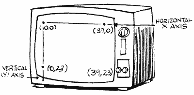
This is the location of the place in memory where the data is kept that goes onto the screen. Each number in memory represents one character on your TV or several pixels if in a graphics mode. The value at memory location SAVMSC goes at the upper left-hand corner of the screen. The next number in memory goes on the character to the right and so on until the whole row is filled (40 characters in mode 0). The next memory location then goes to the left side, one row down.
When you do I/O to the screen, the OS uses this address to figure out where to PLOT and PRINT. So, for example, the following line will put the letter "A" in the upper left-hand corner of your graphics zero (or one or two) screen.
But wait, you say. CHR$(33) doesn't give us an "A"; what's going on here? I'll tell you. The Atari stores the characters in memory in a different order than the ATASCII order (which is what CHR$ uses). See CHRORG (57344) to find out how to convert from one to the other. Anyway, the values in screen memory represent the internal character order rather than the ATASCII one.
If you're not using a text mode, the values you poke to the screen will, obviously, affect the pixels on the screen (the dots on the screen). A pixel is represented by one, two, or four bits. See location DMASK (672) to find out what bits in a byte affect which pixels in each mode (that was easy for me to say). Then try POKEing around. You may want to check CHRORG again; it has an example of using such POKEs to get characters on the screen in graphics mode eight.
OK, so now you know how to change the first character on the screen. What if you want to change the sixth character on the tenth row; how do we know how to find it? Figure 5 shows how many bytes per row are required for each graphics mode.
| MODE | 0 |
1 |
2 |
3 |
4 |
5 |
6 |
7 |
8 |
9-11 |
| BYTES/ROW | 40 |
20 |
20 |
10 |
10 |
20 |
20 |
40 |
40 |
40 |
FIGURE 5. Number of bytes per row
Now, if you want to change character X in row Y, just multiply Y by the number of bytes per row for the mode you're using and add X (don't forget that the first row and column are numbered zero, not one). Add this value to the address in SAVMSC, and POKE away. For example, let's put the letter "B" in the middle of a graphics zero screen (row 11, column 19):
100 GRAPHICS 0
110 SCREEN=PEEK(88)+PEEK(89)*256
120 POS=11*40+19
130 POKE SCREEN+POS,34
We want to make sure that we don't try and change a byte that isn't part of the screen, so let's add another line to our chart, this one giving the number of rows in each mode. We'll also multiply the number of rows times and bytes per row to get the total number of bytes taken up by the screen memory (Figure 6).
| MODE |
0 |
1 |
2 |
3 |
4 |
5 |
6 |
7 |
8 |
9-11 |
| ROWS |
24 |
24 |
12 |
24 |
48 |
48 |
96 |
96 |
192 |
192 |
| BYTES |
960 |
480 |
240 |
240 |
480 |
960 |
1920 |
3840 |
7680 |
7680 |
FIGURE 6. Screen memory requirements
Now these values, when added to the address in SAVMSC, will give you the value of the first byte after the end of screen memory. What they don't tell you is how much memory the whole graphics mode takes up. Why not? Because they don't take into account the display list (see SDLSTL [560,561]) and a few bytes that get trapped in the middle of everything. So how do we get this total memory amount? Well, it turns out that RAMTOP (106) points to the top of free memory, which coincides with the first byte after the end of screen memory. MEMTOP (741,742) points to the top of BASIC memory, which coincides with the first byte before the display list. So, if we subtract MEMTOP+1 from RAMTOP*256 (RAMTOP is in terms of pages), we'll get the total memory required. I'll save you the trouble and just give you the values. Our final chart is Figure 7.
| MODE | 0 |
1 |
2 |
3 |
4 |
5 |
6 |
7 |
8 |
9-11 |
| BYTES/ROW |
40 |
20 |
20 |
10 |
10 |
20 |
20 |
40 |
40 |
40 |
| NO.
OF ROWS |
24 |
24 |
12 |
24 |
48 |
48 |
96 |
96 |
192 |
192 |
|
TOTAL SCREEN BYTES |
960 |
480 |
240 |
240 |
480 |
960 |
1920 |
3840 |
7680 |
7680 |
|
TOTAL MODE BYTES (NORMAL SCREEN) |
992 |
672 |
420 |
432 |
696 |
1176 |
2184 |
4200 |
8138 |
8138 |
| (SPLIT
SCREEN) |
... |
674 |
424 |
434 |
694 |
1174 |
2174 |
4190 |
8112 |
FIGURE 7. Screen requirements chart
You may have told yourself by now that you can change the values in SAVMSC and thereby change where the screen is. And if you can change where the screen is, you can keep more than one screen in memory at the same time. Well, you're half right. You definitely can have more than one screen in memory at the same time, but unfortunately SAVMSC only tells the OS where to PRINT and PLOT (and the like) to; it doesn't tell the computer what to display on the television screen. Fortunately, there is another pair of locations that tell what to display, and the word "display" should tip you off to where they are; they're in the display list (this is kind of like adult Sesame Street, isn't it?). Specifically, they're the fifth and sixth bytes in a normal (unaltered by you) display list. Try the following:
100 DLIST=PEEK(560)+PEEK(561)*256
110 LOW=PEEK(DLIST+4)
120 LOW=LOW+1
130 IF LOW=256 THEN LOW=O:POKE DLIST+5,PEEK(DLIST+5)+1
140 POKE DLIST+4,LOW
150 FOR DELAY=1 TO 10:NEXT DELAY
160 GOTO 120
This will move the starting address of the screen one byte forward at a time, having the effect of swallowing up whatever was on the screen when you ran it. Press SYSTEM RESET to stop it and get everything back to normal.
A few things to note here. First, if you let this run for a while (get rid of line 150 to make it happen faster), the screen will suddenly fill up with a whole bunch of garbage. This "garbage" is actually your BASIC cartridge! The starting screen address has been moved so far forward that it has now entered the BASIC zone. You may have astutely noted that the garbage didn't scroll onto screen smoothly, but rather just sort of suddenly appeared. This is because the screen memory has committed a no-no. It has crossed a 4K boundary. What is a 4K boundary? It's the boundary between one group of 4096 bytes and the next one. How do you tell where one is? Well, first of all the address of a 4K boundary is a multiple of 4096. Better yet, if you're working in hexadecimal, the leftmost digit in the four-digit hex number is the "4K digit" (this is not an official term). When it gets changed, a 4K boundary has been crossed. OK? In any case, the whole purpose of this explanation was simply to tell you that the screen memory is not allowed to cross over a 4K boundary. The GRAPHICS command usually takes care of this for you, but if you're setting up more than one screen, you'll have to be careful.
Going way back to our program example, you should also note that despite what's happening on the TV set, the OS still thinks that the screen is where it was originally, since we haven't changed SAVMSC. If you expect the OS to keep up with you, change SAVMSC as well as the display list.
Finally (and you thought it would never end), before we move onward and upward, a few bits of memory trivia. The address of the text window memory can be found at TXTMSC (660,661). And, in case you thought you weren't going to get a good multiple screen example, you're right. Just kidding.
99 REM Get everything set up
100 GRAPHICS 1:PRINT #6;"THIS IS SCREEN ONE"
110 DLIST1L=PEEK(560):DLIST1H=PEEK(561)
120 DLIST1=DLIST1L+DLIST1H*256
130 SCRMEM1L=PEEK(DLIST1+4):SCRMEM1H=PEEK(DLIST1+5)
140 POKE 106,DLIST1H-4
150 GRAPHICS 2:PRINT #6;"THIS IS SCREEN TWO"
160 DLIST2L=PEEK(560):DLIST2H=PEEK(561)
170 DLIST2=DLIST2L+DLIST2H*256
180 SCRMEM2L=PEEK(DLIST2+4):SCRMEM2H=PEEK(DLIST2+5)
189 REM Do the flipping
190 POKE 560,DLIST1L:POKE 561,DLIST1H
200 POKE 88,SCRMEM1L:POKE 89,SCRMEM1H
210 GOSUB 1000
220 POKE 560,DLIST2L:POKE 561,DLIST2H
230 POKE 88,SCRMEM2L:POKE 89,SCRMEM2H
240 GOSUB 1000
250 GOTO 190
999 REM Pause between screens
1000 FOR PAUSE=1 TO 200:NEXT PAUSE
1010 RETURN

Sorry, but no explanation for this one. You should be able to figure it by yourself. I will, however, give you the following lines which you may want to add to make the screen look a little less messy:
235 POKE 559,34
1005 POKE 559,0
OLDROW
90 005A
OLDROW is the last row the graphics cursor was on. It gets its value from ROWCRS (84). DRAWTO and the FILL command (XIO 18) use it to determine their starting row.
OLDCOL
91,92 005B,005C
The last column the graphics cursor was on. Guess where this one gets its value from? You got it, COLCRS (85,86). It gets used the same way as OLDROW does.
OLDCHR
93 005D
When you move the cursor all over the screen, isn't it nice how it doesn't erase characters as it goes over them? Thank this guy for that; OLDCHR holds the value of the character under the cursor so it can be put back when the cursor moves on.
OLDADR
94,95 005E,005F
OLDCHR is great, but the OS has to know where to put it (no suggestions, thank you). OLDADR is the address in screen memory of the current cursor location and is used to help restore the character under the cursor.
NEWROW
96 0060
Out with the OLD and in with the NEW! This is the row that DRAWTO and FILL will draw to or fill to. It is initialized to the value in ROWCRS (84).
NEWCOL
97,98 0061,0062
Same as the preceding except this is the column to draw or fill to and is initialized to the value in COLCRS (85,86).
LOGCOL
99 0063
More cursor position stuff, this time for the benefit of the display handler. LOGCOL tells the position of the cursor within the current logical line. It is equal to the number of rows the logical line has filled so far times 40, plus the current value of COLCRS. Since a logical line can fill up to three rows, this gives LOGCOL a range of 0 to 119.
See BUFCNT (107) for the character length of the logical line.
ADRESS
100,101 0064,0065
A temporary storage location used by the display handler for so many things that it made my mind spin and I forgot what they were.
MLTTMP
102,103 0066,0067
More temporary storage, with aliases OPNTMP and TOADR.
SAVADR
104,105 0068,0069
Also know as FRMADR. Also used for temporary storage. Also not significant enough to explain (look at the OS listing if, for some reason, you really care).
RAMTOP
106 006A
As you probably guessed, this points to the top of RAM. It gets its value from TRAMSZ (6) during the powerup operation, as does RAMSIZ (740). Big deal, right? Wrong.
If you're doing custom character sets, player/missile graphics, or anything else where you need a fairly large amount of memory that is safe from BASIC and the OS, RAMTOP is going to save your tush. You see, the OS doesn't care if RAMTOP isn't really the top of memory, so you can change its value and make the OS think that the top of memory is lower than it really is. Then you can go ahead and use the extra locations between RAMTOP and RAMSIZ for whatever you want. It's done something like this:

1. Decide how many pages of memory you want to protect. Remember that a page is 256 bytes (RAMTOP is in terms of pages).
2. POKE RAMTOP with the value in RAMSIZ minus the number of pages.
3. Do a GRAPHICS call. If you don't, your "protected" memory will be in the middle of the screen memory. The GRAPHICS call moves the screen below the new RAMTOP.
4. The locations from RAMTOP (times 256 remember) to RAMSIZ (times 256, minus 1) are now your very own.
Easy, isn't it? Well, not quite. First of all, the first 800 bytes after RAMTOP aren't really safe. The OS scrolls the text window as if it were an entire GRAPHICS zero screen (this saves having to write a special routine for the text window). This means that the OS tries to scroll 20 rows (times 40 bytes per row) after RAMTOP. This is fine normally, because there is no more RAM after RAMTOP that would get messed up. Unfortunately, when you have moved RAMTOP, your RAM is in jeopardy. The first 800 bytes of it, that is. The solution, if you're using a graphics mode with a text window, is just to protect four more pages than you need, and not use the first 1024 (to be safe) after RAMTOP. If you're not using a text window, you still have to protect an extra page, because the first 64 bytes aren't safe for other reasons.
You also have to be careful that the new RAMTOP isn't less than MEMTOP (741,742), since MEMTOP points to the top of your program area.

Confused by "Saving Memory Areas?"
Lastly, because of the 4K boundary problem mentioned under SAVMSC (88,89), you should move RAMTOP by at least 16 pages (16*256=4K) if you're using graphics mode seven or higher.
You can also use MEMLO (743) to protect a different part of memory.
First of all, there is a very simple reason to "protect" an area of memory. If you POKE numbers into memory that currently has nothing in it, then run your program, you may find your data changed when you go to use it. The reason is that BASIC has to move things around as it works. The only way to be sure you have a completely safe area is to move the pointer (106) down so BASIC thinks the top of memory is lower than it really is.
BUFCNT
107 006B
This keeps count of the number of characters currently in the logical line
BUFSTR
108,109 006C,006D
The starting address (in terms of row and column) of the current logical line buffer. It is initialized to the values in ROWCRS and COLCRS when the line is started.
BITMSK
110 006E
The display handler uses BITMSK to mask off bits during the bitmapping process. What? For those of you not into machine language, a dot on the screen (in the graphics modes, not the text modes) is represented in memory by two bits (one bit in graphics mode eight). So, since two bits are only part of a byte, the OS has to have a way of changing bits without changing the other parts of the byte. The process it uses is called "masking," and uses the AND and ORA assembly language commands to clear and set individual bits respectively. See a book on assembly language for a more detailed explanation of these two commands. Bit mapping, by the way, refers to the whole process of manipulating the bits to come up with the desired graphics.
SHFAMT
111 006F
Masking (explained in the previous location description) can be a pain in the byte (sorry). The problem is not in the actual ANDing and ORAing, but rather in getting the bits ready to be masked into the byte, or dealing with them after they've been masked out. Think about it for a second. In graphics mode eight, for example, each bit represents a dot on the screen (called a "pixel"). That means that once you mask out the bit you're interested in, there are eight possible positions it could be in. You obviously don't want to have to write the code to deal with eight different cases. Well, Atari didn't either, so they came up with SHFAMT. SHFAMT is used to shift the bits to the right, one bit at a time, until the bits you are interested in are all the way over to the right (right justified). It's easier to deal with them there. Once you're done having your way with them, SHFAMT helps you get them back to their proper places.
OK, we've got a cute explanation, but what's really going on? SHFAMT initially gets the value in DMASK (672), which is used to mask out the desired pixels. SHFAMT is then shifted to the right (LSR) one bit. If a bit hasn't fallen out of the byte in the process (the carry flag is clear), the masked-out bits are also shifted to the right one bit and the whole thing is repeated. If a bit did fall out, then the masked-out bits are right justified. To get the bits back to their proper position, SHFAMT is restored to the value in DMASK and the same thing happens except this time the masked-out bits are shifted to the left (ASL) one bit at a time (SHFAMT is still shifted to the right though). Then the bits are ready to be masked back into the display byte.
This is a very important and powerful process to understand if you're doing your own bit mapping. Check your OS listing and DMASK for more details.
ROWAC
112,113 0070,0071
ROWAC, along with COLAC (next), are essentially graphic workspaces, used primarily in the "what point do we plot next?" process. ROWAC, of course, is used in the row calculations.
COLAC
114,115 0072,0073
Used in column calculations for point plotting. See ROWAC.
ENDPT
116,117 0074,0075
ENDPT is initialized to either the value in DELTAR (118) or the one in DELTAC (119,120), depending on which is larger (it gets the larger of the two). It is then used to figure out when the final row or column in the line we're drawing has been reached.
DELTAR
118 0076
DELTAR is the absolute value of the difference between OLDROW (90) and NEWROW (96). In other words, it's the number of rows we're going to be drawing across.
DELTAC
119,120 0077,0078
The number of columns we're going to be drawing across. Determined by subtracting OLDCOL (91,92) from NEWCOL (97,98) and taking the absolute value.
ROWINC
121 0079
When the OS computed DELTAR above, it took the absolute value of the result of NEWROW minus OLDROW. The sign of this result, however, is also important to us because it tells the direction we'll be drawing in. ROWINC is one if the sign was negative (we'll be drawing up), and 255, (which also equals minus one in two's complement arithmetic) if it was positive (we'll be drawing down).
COLINC
122 007A
If NEWCOL minus OLDCOL is negative (we'll be drawing left), COLINC is set to one. If it's positive (we'll be drawing right), COLINC is set to 255.
Note that together DELTAR, DELTAC, ROWINC, and COLINC define the slope of the line to be drawn.
SWPFLG
123 007B
If you're using a split screen mode, it's easier for the OS to print to the text window if it has all the cursor information for it in locations 84 to 95. But it also has to remember the cursor information for the main part of the screen, so what it does is swap the two. SWPFLG equals zero if they haven't been swapped, 255 if they have.
The text window information is kept in locations 656 to 667.
HOLDCH
124 007C
A character that has been typed in from the keyboard goes here so the OS can check out just what kind of character it really is (CTRL, SHIFT, etc.).
INSDAT
125 007 D
More display handler temporary storage. I'll even tell you what it's used for; it holds the character under the cursor and is used for end of line detection. Wasn't that exciting?
COUNTR
126,127 007E,007F
Well, here we are back at drawing a line. COUNTR tells how many points have to be plotted before the line is finished. It starts off with the same value as ENDPT (116,117). Then, every time a point is plotted on the line, it gets decremented by one. When it gets all the way down to zero, the line is finished and we can all go home.
The remaining zero page locations (128 to 255) are used by BASIC, with some free for your use. The breakdown looks something like figure 8.
| 128-145 |
($0080-$0091) | |
BASIC program pointers |
| 146-202 |
($0092-$00CA) | Various BASIC locations | |
| 203-209 |
($00CB-$00D1) | Free for your use | |
| 210-211 |
($00D2-$00D3) | Reserved for use by BASIC | |
| 212-255 |
($00D4-$00FF) | Used for
floating-point arithmetic |
FIGURE 8. Location 128-255 breakdown
ERROR: IMAGE NOT FOUND: page_zero-15.gif
If you're using a language other than
BASIC, check its instruction
manual to find out which of these locations it uses.
If you are programming in machine
language, and not using a cartridge,
all 128 bytes here are probably free for your use. Check your
assembler's manual.
LOMEM
128,129
0080,0081
LOMEM points to the beginning of the
RAM available for BASIC programs
(in other words the end of the OS RAM). It gets the same value as MEMLO
(743,744) initially, and every time the BASIC "NEW" command is used.
Although this implies that its value can differ from that of MEMLO,
this doesn't seem to be the case. The only difference between LOMEM and
MEMLO appears to be that BASIC uses LOMEM while the OS uses MEMLO.
The first 256 bytes after LOMEM are
used as a buffer by BASIC for the
tokenization process. Tokenization refers to the process of taking your
program and scrunching it up so it takes up as little space as
possible. Essentially, each command and variable is replaced with a
number (called a "token"). That way, it only takes one byte to store a
command, rather than one byte for each letter in the command (this is
an extremely simplified description; see De Re Atari for a complete
play-by-play). Note that the SAVE command saves the program in
tokenized form, while LIST saves it just the way you typed it in.
That's why a SAVEd program will be shorter than a LISTed one.
Incidentally, if you SAVE a program, the values in locations 128 to 141
are saved along with the program.
BASIC also uses the buffer as a stack
to evaluate expressions (8+2 is
an expression), in which case it calls it ARGOPS. See RUNSTK (142,143)
for a description of stacks.

VNTP
130,131 0082,0083
This points to the table where the variable names are kept. The variable names are stored in the order they were typed (which is not the same as the order the program uses them) in ATASCII. To mark the end of a variable name (so you know when the next one starts), the last character of each variable (a letter or digit for regular variables, a "$" for string variables and a "(" for arrays) is stored in inverse video (add 128 to the ATASCII value of the character). Enough talk, here's an example of how to print the variable list:
100 VNTP=PEEK(130)+PEEK(131)*256
110 VNTD=PEEK(132)+PEEK(133)*256
120 FOR LP=VNTP TO VNTD-1
130 CH=PEEK(LP)
140 IF CH>127 THEN PRINT CHR$(CH-128);" ";:GOTO 160
150 PRINT CHR$(CH);
160 NEXT LP
VNTD (next location), of course, holds the address of the end of the variable name table (plus one).
There are a few other useful things you should know about the variable name table. First of all, if you used any variables while you were writing your program (including those used in the immediate mode) but don't use them now that the program is done, they're still in the table taking up space. In order to get rid of it, you must LIST your program to disk or cassette, type NEW, and then ENTER the program back in (this has the effect of typing in the final version of the program from scratch).
Second, you can have up to 128 different variables in your program. When BASIC tokenizes the program (see LOMEM), it replaces each variable name with a number equal to the position of the variable in the name table plus 128 (128 if it's the first variable in the table, 129 if it's the second, and so forth). This saves a lot of memory.
Third and last, there's a neat trick you can use to make your program look like garbage when it's listed. All you have to do is change all your variable names to a RETURN character. This will protect your programs from being looked at by others. The following routine will do it for you. You can't get things back to normal, so make sure you have an original version of your program saved before you try this:
30010 VNTD=PEEK(132)+PEEK(133)*256
30020 FOR LP=VNTP TO VNTD
30030 POKE LP,155
30040 NEXT LP
VNTD
132,133 0084,0085
The address of the first byte after the end of the variable name table.
VVTP
134,135 0086,0087
Now we know where the variable names are stored and we're about to find out where the variable values are stored. VVTP, you see, points to the variable value table (we'll call it the VVT).
The Atari has three different kinds of variables. There are the scalars (like X, HI, and FUNSTUFF),the arrays (like JULY (4) and SWEET (16,2)), and the strings (like MONEY$). Each of these has a different representation in the VVT, but they all take up eight bytes per variable. Let's take a look at how those bytes are used:
The first byte tells what kind of variable it is. Scalars get a 0, arrays a 65, and strings a 129. Actually, if you forgot to DIMension the array or scalar in the program (shame on you), you can knock one off the preceding value given above.
The second byte tells what variable name we're talking about here. It's the position of the variable in the variable name table (0 for the first variable, 1 for the second, and so on up to a maximum of 127).
If we're dealing with a scalar, the remaining six bytes give its value in Binary Coded Decimal (BCD). I suspect a quick explanation is necessary here. BCD, as the name implies, is a way of storing a decimal number in binary. Everything alright so far? Good. Atari doesn't seem to follow the standard 6502 BCD format, so I'll give the Atari breakdown. The first byte is the exponent; 64 means 0, 63 means minus 2 (65 for plus 2, 66 for plus 4) and so forth. Add 128 if the value of the variable is negative. The second byte gives the two decimal digits to the left of the decimal point (in BCD, the upper nibble gives one digit, the lower nibble gives a second). The last four bytes give the eight digits to the right of the decimal point. If this makes no sense to you, look up BCD in any introductory book on machine language programming. It probably still won't make sense.
Back to the VVT. If the variable isn't a scalar (after the preceding description, pray that it isn't), then the third and fourth bytes give an offset into the string/array area (see STARP [140,141]). This offset points to the beginning of the data for that variable (relative to the beginning of the string/array area, of course).
If it's an array we're dealing with, the fifth and sixth bytes give the first dimension and the seventh and eighth give the second. No BCD here, just plain old binary. In case you're wondering what I'm talking about, a dimension is the number(s) plus one you use in BASIC's DIM statement. For example, the first dimension in DIM A(5,7) is six, and the second is eight. The reason that one is added is because A(0,0) is a valid array element and, therefore, the array in our example is actually six elements by eight, not five by seven.
If it's not an array (and it wasn't a scalar), then it must be a string. In that case the fifth and sixth bytes give its current length and the seventh and eighth its DIMensioned length (up to 32767).
Note that the value of VVTP will change everytime a new variable is added.
STMTAB
136,137 0088,0089
The variable names and their values are all set, now where's the program? STMTAB tells you just that. It holds the address of the statement table, which is just a fancy name for your tokenized program (plus the last line you typed in without a line number, called the "immediate mode line").
The statement table contains each of the tokenized lines, one after the other. As I mentioned earlier, you should see De Re Atari for a complete description of the tokenization process (which takes place in a buffer pointed to by LOMEM [128,129]). I will, however, fill you in on a few useful tidbits of information.
The first two bytes of each tokenized line give you the line number (in binary). The immediate mode line has a line number of 32768. The third byte tells you the number of bytes from the beginning of this line to the beginning of the next line. The fourth byte tells you the number of bytes from the start of the line to the start of the next statement (in case you use the ":" to put more than one statement on a line), and that's all you'll get out of me.
Try the following to tell you how many lines you have in your program:
30000 STMTAB=PEEK(136)+PEEK(137)*256
30010 LINES=0
30020 LINENO=PEEK(STMTAB)+PEEK(STMTAB+1)*256
30030 IF LINENO=30000 THEN PRINT "Your program has "; LINES;" lines.":END
30040 LINES=LINES+1
30050 STMTAB=STMTAB+PEEK(STMTAB+2)
30060 GOTO 30020
STMCUR
138,139 008A,008B
STMCUR is a pointer into the statement, which BASIC relies on when it needs to refer to particular tokens while processing a line in the statement table. When a program isn't running, and BASIC is just sitting around, it points to the beginning of the immediate mode line.
Try the following to create a program that can't be LOADed, only RUN:
32767 POKE PEEK(138)+PEEK(139)*256+2,0:SAVE "D:RUNONLY":NEW
You can use any filename, of course (and can substitute "C:" for "D:" if you're using cassette). Make sure this is the last statement in your program. If you want, you can include the routine for changing variable names (see VNTP [130,131]) right before this line to further protect your program.
To use the routine, GOTO 32767. Then RUN "D:RUNONLY" or RUN "C:RUNONLY" (substitute your filename for RUNONLY).

STARP
140,141 008C,008D
STARP holds the address of the string/array area, which is where all the string characters and array values are stored (see VVTP [134,135] to find out how to determine where each variable is within this area). It also points to the end of your BASIC program, which should hint to you that its value will change as your program changes.
Array values are stored in six-byte BCD form (see VVTP [134,135]), while strings use one byte per character. If you DIMension an array such as A(x), where x is the number of elements in the array, then it will take up x*6 bytes in the string/array area, regardless of how many of the elements you use. The same goes for strings. If you DIMension ANS$(y), then y bytes will always be reserved for it in the string/array area, even if you never use it. For this reason, you should be careful when DIMensioning variables and should also make sure that all unused variables are removed from the final version of your program (see VNTP [130,131]).
A few bits of miscellanea. The beginning address in the string/array area of the data for a string is the same as the address you get with the ADR function. More importantly, there is a way you can save a lot of memory using STARP. Here's the scoop.

A lot of times our programs have strings or arrays in them that always get initialized to the same lengths and values. It may be a string that holds a redefined character set or a machine language routine, for example. Anyway, somewhere in your program you have an initialization routine and the data for the string or array, right? Well, you just found out that the data is also stored in the string/array area. That means that it's in memory twice (the other time is in the tokenized program listing). That's very bad, and I'm going to show you how to do something about it.
As mentioned, STARP also points to the end of your BASIC program. What happens if we change STARP so that it points to the end of the data for the strings/arrays in question? BASIC will think it's part of the program, which means we can SAVE that part of the string/array area with the program! And that means no more need for initialization, so we can get rid of the initialization part of the program. Here's an example of how to do it:
99 GOTO 200:REM You should GOTO 100 the first time through
100 DIM TEST$(32)
110 TEST$="We'll save this with the program"
120 STARP=PEEK(140)+PEEK(141)*256
130 NWSTARP=STARP+32
140 HIGH=INT(NWSTARP/256):LOW=NWSTARP-256*HIGH
150 POKE 140,LOW:POKE 141,HIGH
160 SAVE "D:TEST.BAS"
170 STOP
200 STARP=PEEK(140)+PEEK(141)*256
210 NWSTARP=STARP-32
220 HIGH=INT(NWSTARP/256):LOW=NWSTARP-256*HIGH
230 POKE 140,LOW:POKE 141,HIGH
240 POKE 142,LOW:POKE 143,HIGH
250 POKE 144,LOW:POKE 145,HIGH
260 DIM TEST$(32)
270 TEST$(32,32)="m"
280 PRINT TEST$
290 STOP
You're probably wondering how to use this monstrosity, so I'll be a nice guy and tell you. There are two basic parts to it. The first, lines 100 to 170, initialize the string, move STARP to the end of the string, and save everything to disk (you can use C: as well). You could alternately get rid of these lines right before you save the program, because they won't be necessary any more. The second part, from line 200 on, restores STARP and a few other locations that were affected, redimensions the string, and sets the last character so that BASIC knows how long the string is. Now we can print TEST$ and verify that it was indeed saved with the program!
Ok, now how do you adapt this to your own program? First of all, make sure the strings/arrays you want to save are the first variables you use in the program (use VNTP to get rid of unused variables). DIMension and initialize them (you can use a GOSUB to the initialization; it doesn't have to be at the beginning of the program). Now figure out how much memory they take up: one byte for each character, six for each array element. Add this to the current value in STARP and store the new value back in STARP. STOP the program. Get rid of the part of the program that did all of the preceding stuff (including the part for initializing). Add lines 200 to 270 at the beginning of the program (making the appropriate changes in lines 210, 260, and 270) and then save it to disk. That's it.
One last tidbit. There is a quick, easy, little known way of filling a string variable with the same character. It works because of the way BASIC is written. Try this:
110 FILL$(1)="F"
120 FILL$(800)="F"
130 FILL$(2)=FILL$
140 PRINT FILL$
RUNSTK
142,143 008E,008F
This one is a pointer to the runtime stack. What is a "runtime stack"? Let's start off with a quick explanation of a stack.
Every seen a stack of trays in a cafeteria? Customers take trays off the top, cafeteria people put trays on the top, if you're not lucky there'll be a mad rush of people and by the time you get to the stack there are none left and the cafeteria people are nowhere to be seen. Well, a computer stack is the same thing, except it uses memory locations instead of trays and there are no cafeteria people. A special memory location is used to point to the current top of the stack.
Now you know what a stack is, so let's talk about the runtime stack. Runtime just means that it's used while the program is running. When you use a GOSUB or a FOR/NEXT loop, BASIC has to be able to remember certain things, so it puts them on the stack until it needs to refresh its memory. Now you need to know what exactly gets put on the stack.
For each GOSUB encountered, four bytes are put on the stack (they are taken off when BASIC RETURNS from the subroutine). The first byte is a zero and tells BASIC that this is a GOSUB. The second and third give the line number that the GOSUB was on, and the last one is an offset into the line so that BASIC knows where to continue from after the RETURN.
FOR/ NEXT loops are a little more complicated; they require 16 bytes to be put on the stack. The first 6 bytes give the number (in BCD) that the counter in the loop can go up TO. The second 6 give the STEP value (also in BCD). The thirteenth byte gives the variable number plus 128 of the counter variable. The next two give the line number that the FOR statement was on, and the last one gives the offset within that line of the FOR. These values remain on the stack until the FOR/ NEXT loop is complete.
There is one exception to the preceding two paragraphs. A BASIC POP statement will take the top entry off the stack, be it a GOSUB or a FOR/NEXT. You should make sure you POP the stack if you have to leave a FOR/NEXT loop before it's finished or a GOSUB before the RETURN.
Don't forget that the stack is constantly changing, so its size will vary.
Lastly, since the beginning of the runtime stack is also the end of the string/array area, BASIC also calls it ENDSTAR. OK?
MEMTOP
144,145 0090,0091
Two uses for this one. First, relevant to the last location, MEMTOP is also called TOPSTK and points to the end of the runtime stack. Since the runtime stack is the last section of memory used by your BASIC program, MEMTOP is a pointer to the end of your BASIC program (which makes sense, right?). The memory locations from the address in MEMTOP plus one, all the way up to the display list (see SDLSTL [560,561]), are free for your use (but don't forget that the value in MEMTOP will change during program execution, since the runtime stack will be growing and shrinking).
For those of you who are still alert, don't confuse this MEMTOP with the MEMTOP at 741 and 742. This is the BASIC MEMTOP; the other is the OS MEMTOP.
The BASIC cartridge uses locations 146 to 202 for various uses, not all of which are worthwhile reporting on. With the following exceptions, of course.
FORLN
160,161 00A0,00A1
FORLN holds the line number of the current FOR statement encountered. For example,
100 FOR X=1 TO 25
110 NEXT X
120 PRINT PEEK(160)+PEEK(161)*256
LSTPNT
173,174 00AD,00AE
List pointer. Contains the location of the line being LISTed. When you just type LIST, you find 32767 here.
DATLN
182 00B6
Points to the number of the item within the DATA statement. This means we are currently reading the first number, the second, etc. Try this program:
20 READ A
30 ? PEEK(182)
40 NEXT I
50 DATA 1,2,3,4,5,6,7,8
DATALN
183,184 00B7,00B8
DATALN holds the line number of the DATA statement that was last READ. For example,
100 READ A
110 PRINT PEEK(183)+PEEK(184)*256
1000 DATA 10
You can use DATALN in an error-trapping routine to find out where a READ error occurred.
STOPLN
186,187 00BA,00BB
STOPLN holds the line number that the program was on when the program STOPped, the BREAK key was pressed, or an error was TRAPped. It is also useful in error trapping routines. Now for our example:
110 NEXT Y
30000 PRINT PEEK(186)+PEEK(187)*256

ERRSAV
195 00C3
This location holds the number of the error that was TRAPped or caused the program to stop. Try this:
10 TRAP 100
20 REM THE REST OF YOUR PROGRAM
.
.
.
100 ?"ERROR #"; PEEK(195):LIST(PEEK(186)+256*PEEK(187))

PTABW
201 00C9
When you print a whole bunch of items, and separate them by commas in the PRINT statement (like PRINT A,B,C$), they get printed on the screen with a bunch of spaces in between them, right? Well, PTABW tells how many spaces to separate them by. In technical terms, that means it tells how many spaces there are between each tab stop on the screen (see TABMAP [675 to 689] if you want to set tabs for the TAB key). It can be set to any value from 3 to 255 but is initialized to 10. Let's look at an example:
110 POKE 201,5
120 PRINT 1,2,3
SYSTEM RESET doesn't restore PTABW to its original value, GRAPHICS doesn't, nothing does. This is a very durable location.
POKEing a zero here will cause the Atari to lock up shop when it encounters a comma in a PRINT statement.
BININT
202 00CA
If you put anything other than a zero here, then going into the immediate mode (i.e. SYSTEM RESET, BREAK, or the program ending) causes the program currently in memory to erase itself - yet another fun way to prevent people from looking at your program (I personally like this one; it's devious).
110 PRINT "Now try LISTing this program"
Noname
203-209 00CB-00D1
These locations are free, free, free for your use if you're programming in BASIC. If you're using a different language, check the accompanying documentation to find out which page zero locations it leaves free.
Noname
210,211 00D2,00D3
These two locations are reserved for BASIC, which means they have no specific use but you should stay away from them.
Return to Table of Contents | Previous Chapter | Next Chapter