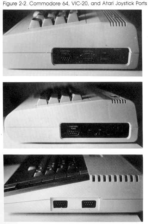
With a basic understanding of how a computer operates, you can now begin exploring the computer's ports, the gateways through which information flows into and out of your computer. The ports are often referred to as I/O ports, which stands for input/output ports. Though there are several different 1/O ports on your computer, the projects in this book use one port in particular, the joystick port.
The joystick port provides plenty of access to your computer for our demonstation circuits. Connectors for this port are also commonly available. They are the same type as those found on joysticks and game paddles-D-subminiature female connectors.
| Control Port 1 |
Control Port 2 (Commodore
64) |
||
| Pin |
Type |
Pin |
Type |
| 1 |
JOYA0 |
1 |
JOYB0 |
| 2 |
JOYA1 |
2 |
JOYB1 |
| 3 |
JOYA2 |
3 |
JOYB2 |
| 4 |
JOYA3 |
4 |
JOYB3 |
| 5 |
POT AY |
5 |
POT BY |
| 6 |
Button A/LP |
6 |
Button B |
| 7 |
+5 volts |
7 |
+5 volts |
| 8 |
Ground |
8 |
Ground |
| 9 |
POT AX |
9 |
POT BX |
The joystick port has nine pins. Pins 1, 2, 3, 4, and 6 are I/O pins. They are connected to wires which may be used to communicate binary (on/off) data. Pins 5 and 9 are used to input analog data-we'll learn more about these pins later in the book. Pin 7 is connected to a +5-volt source, while pin 8 is connected to the power supply ground.
Once you can identify the pins of a control port, your next step is to understand how they can be used. A few homemade "tools" will help.
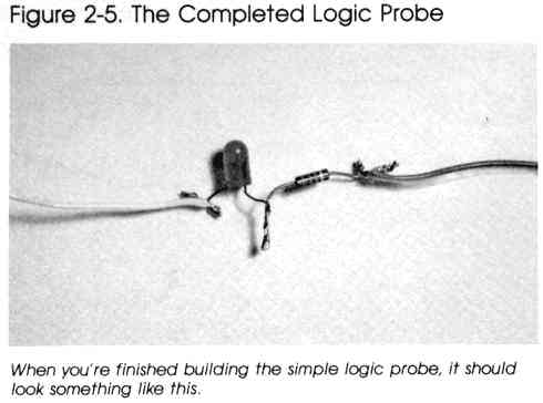
A Simple Logic Probe
A logic probe is a device that lets you "look" into what's going on in a digital circuit. It's a device that tells you whether a 1 (high state) or a 0 (low state) is present at a point in the circuit. A simple logic probe can be assembled from two main components. This logic probe can be used to see how the I/O lines of the control port are used to input information.
To construct the logic probe, you'll need these parts:
| Quantity |
Part |
Part Number |
| 1 |
Light-emitting diode (LED) |
276-041 |
| 1 |
1K ohm resistor |
271-8027 |
| 2 |
Alligator clips |
270-378 |
| You'll also need some stranded
copper wire (about #22 gauge-Radio Shack part number 278-1307) to make
the probe leads, as well as some electrical insulation tape. |
||
(In this book, all part numbers are Radio Shack part numbers.)
| |
Here's the procedure for putting together your
simple logic probe: |
|
1. Cut two pieces of stranded copper wire about
10 inches long. One wire will be the ground lead, while the other will
be the probe lead of this simple logic probe. 2. Strip about a half inch of insulation from each end of both wires and attach an alligator clip to one end of each wire. 3. Solder the free end of one wire to the anode of the light-emitting diode (LED). Usually, the anode leg of an LED is the shorter of the two legs, but this may vary with manufacturers. The wire connected to the LED's anode is the probe lead of the logic probe. |

|
Note: An LED lights up when current passes
through it in the proper direction, which is from anode to cathode. LEDs
come in various colors, but the most common are red and green. An LED
will conduct current in only one direction. It's important that you don't
confuse the anode and the cathode leads. In fact, if an LED fails to work
in a circuit, the first thing to check is whether it's been installed correctly
(see Figure 2-3). The cathode lead is usually the longer of the two leads.
|
|
|
4. Solder the cathode of the LED to one end
of the 1K ohm resistor. 5. Solder the other end of the 1K ohm resistor (brown, black, and red bands) to the free end of the second wire. This second wire is now the ground wire of the logic probe. 6. To complete your simple logic probe, cover your soldered connections with some electrical insulation tape. This will prevent short circuits from occurring while you use your probe. |
|
|
Note: Resistors limit the flow of electricity
in a circuit and are measured in ohms. The value of a resistor is indicated
by its colored stripes-usually there are four. The first two stripes'
colors represent numbers as determined by the resistor color code (see
Table 2-1). These numbers are the first two digits of the resistor value.
The third stripe is the multiplier. The number corresponding to the multiplier
color is the power of ten by which the first two numbers are multiplied
(an easy way to remember it is simply to add x number of zeros to the first
two numbers, where x is the multiplier color's value). All three numbers
are combined to give the value (in ohms) of the resistor. Thus, a resistor which has as its first three stripes (as the one you're working on has) Brown Black Red will have a resistance of 1000 ohms. The brown stripe provides the 1, the black stripe gives the first 0, and the red stripe provides the next two 0's (10 X 102). The fourth stripe represents the resistor's tolerance. The tolerance gives the range, plus or minus, which the actual value of the resistor will be within when compared to the strict value indicated by the color bands. The color of this stripe can be gold, silver, or salmon. The tolerances are plus or minus 5, 10, and 20 percent respectively. Sometimes you won't find a tolerance stripe on a resistor. This means that the resistor has a tolerance of plus or minus 20 percent. If you have a resistor with brown, black, red, and silver stripes, for example, you have a 1000 ohm (1K ohm) resistor with a 10 percent tolerance. The actual value of the resistor is thus between 900 and 1100 ohms. The circuits in this book can all use resistors with a 20 percent tolerance or better. |
Table 2-1. Resistor Color Codes
| Color |
Value |
| Black |
0 |
| Brown |
1 |
| Red |
2 |
| Orange |
3 |
| Yellow |
4 |
| Green |
5 |
| Blue |
6 |
| Violet |
7 |
| Gray |
8 |
| White |
9 |
| Tolerance Bands |
|
| Color |
Tolerance |
| Gold |
± 5 percent |
| Silver |
± 10 percent |
| Salmon |
± 20 percent |
| None |
± 20 percent |
Resistors also have power ratings, which describe the amount of energy (measured in watts) which the resistor can safely handle. For the projects in this book, you may use 1/4- or 1/2watt resistors. A resistor, unlike many other circuit components, may be connected in either direction in a circuit.

|
Using the simple logic probe is very easy. Attach
the ground lead of the logic probe to the power supply ground of the digital
circuit you're testing. Then simply touch the tip of the probe lead to
a point in the circuit. If the point has a voltage of something greater
than the barrier voltage of the LED, usually about 0.7 volts, the LED will
glow. You can assume the point is at a logic high state (a 1). If the point
is at a voltage level less than 0.7 volts, current will not flow through
the diode, the LED stays off, and you can assume a logic low state (a 0)
is present. (Of course, a zero indicates a voltage level less than 0.5 volts,
so a problem could still exist with the circuit under test and not be detected
by this simple tester.) |
To use the logic probe to examine the joystick port,
a connector is required-the next simple tool.
A Connector for
the Joystick Port
The actual connector that plugs into the joystick port is a D-subminiature
female, 9-pin connector. Stranded copper wire (#22 gauge) should be soldered
to the terminals of the connector for easier access.
Here's what you'll need:

|
The procedure is quite simple. |
|||||||||
|
|
1. Cut six pieces of stranded copper wire about
24 inches long and strip about 1/4 inch of insulation from each end. (You
may wish to use ribbon cable instead of wire to avoid a tangle.) 2. Solder a wire to the terminals of pins 1, 2, 3, 4, 6, and 8 of the 9-pin plug. 3. Tape a tag to the opposite end of each wire with the number of the pin it's attached to. This will save you some time later. |
|||||||||
|
|
To use your logic probe with the connector,
attach the ground lead of the probe to the wire from pin 8. |
|||||||||
|
|
While your computer is turned off, insert the
plug into the joystick port. (You should always make sure that the computer
is turned off whenever you insert a plug into any of the I/O ports.) If
you're using a Commodore 64 or Commodore 128, insert the plug into joystick
port 2 on the right side of the machine. If you have an Atari computer,
insert the plug into joystick port 1. |
|||||||||
|
|
Warning: Before turning on your computer, make
sure that none of the wires touch each other. If any wires are touching,
your computer could be damaged. Be particularly careful to inspect the
wires from pins 7 and 8-they should never be in contact. If they are, the
computer's power supply could be damaged. |
|||||||||
|
|
Touch the end of your logic probe to pins 1,
2, 3, 4, and 6. Each time you do this, the LED should glow. This glow
will be very faint, and you may need to shield the LED from room light
to detect the glow at all. This is because of the small amount of current
available at the pins. |
|||||||||
The bits in these registers are normally set on (1) in your computer-that's why the LED of your logic probe should glow faintly when you touch the probe to any of these pins. But how can these pins be used to input information?
Type in and run the appropriate version of Program 2-1.
Program 2-1-Commodore 64/128
EX 10 A=56320:REM FOR PORT 1 USE 56321
FQ 20 IFPEEK(A)AND(2↑0)THEN40
PH 30 PRINT"PIN 1"
RM 40 IFPEEK(A)AND(2↑1)THEN60
SK 50 PRINT"PIN 2"
MG 60 IFPEEK(A)AND(2↑2)THEN80
BP 70 PRINT"PIN 3"
SQ 80 IFPEEK(A)AND(2↑3)THEN100
ER 90 PRINT"PIN 4"
AD 100 IFPEEK(A)AND(2↑4)THEN120
SJ 110 PRINT"PIN 6"
SM 120 GOT020
Program 2-1-VIC 20
AH 10 A=37137
BS 20 IFPEEK(A)AND(2↑2)THEN40
PH 30 PRINT"PIN 1"
GF 40 IFPEEK(A)AND(2↑3)THEN60
SK 50 PRINT"PIN 2"
SA 60 IFPEEK(A)AND(2↑4)THEN80
BP 70 PRINT"PIN 3"
BX 80 POKE 37154,0:IFPEEK(37152)AND(2↑7) THEN100
ER 90 PRINT"PIN 4"
XE 100 POKE 37154,255:IFPEEK(A)AND(2↑5)T HEN120
SJ 110 PRINT"PIN 6"
SM 120 GOT020
Program 2-1-Atari
FP 10 IF STICK(0)<>14 THEN 20
EP 15 PRINT "PIN 1"
BA 20 IF STICK(0)<>13 THEN 30
FB 25 PRINT "PIN 2"
BA 30 IF STICK(0)<>11 THEN 40
FD 35 PRINT "PIN 3"
DH 40 IF STICK(0)<>7 THEN 50
FF 45 PRINT "PIN 4"
DN 50 IF STRIG(0)<>O THEN 60
FI 55 PRINT "PIN 6"
AA 60 GOTO 10
Download (Saved BASIC)
Download / View (Listed BASIC)
When you run the program for your computer, nothing should
seem to happen at first. Take your logic probe and touch the probe to
the wire connected to pin 8. This is the ground from the computer and
should still be connected to the ground lead of the probe. Obviously,
the ground lead and probe lead are at the same potential. The LED will
not light. Since ground voltage corresponds with the off state, everything
is working correctly.
|
|
Now, take the wire from pin 1 and touch its
free end to the wire from pin 8. When you do this, you force the normally
on pin 1 to turn off. Your program tells you this. If you look at the
computer screen, the message, PIN 1 should be displayed on the screen.
As you touch the wires from pin 2, 3, 4, or 6 to the ground, you'll see
a message showing which pin has been set low. By forcing an I/O pin to
logic low, its corresponding bit in the register (a memory location) is
set low as well. Since a program can PEEK into a memory location and check
its contents, software can be written to detect the states (on or off) present
at the control port, then proceed accordingly. In Program 2-1, your computer is sensing which pin you're setting low (by touching the wire from the pin to ground). Then it's taking this input and processing it; in this case it's used to print out messages. The next chapter will use this information to construct a useful input device, a joystick. |
Return to Table of Contents | Previous Chapter | Next Chapter