Artifacting With Graphics 7-Plus
Harry G. Arnold
The technique of artifacting to produce special color effects is often mentioned but seldom explained. One reason for the brevity in instructions is that even though it is possible to achieve high resolution, multiple color, and graphics displays with artifacts, Basic and the Operating System (OS) do not support artifacting in a user-friendly manner. This discussion will present an introduction to television color artifacts similar to that seen in many other places, then proceed to describe a method and program listings to more easily use artifacts in Atari Basic. Because the resolution of the resultant display is half way between GR. 7 and GR. 8 it is often referred to (affectionately) as "Graphics 7-Plus" or GR. 7+. It is in fact Antic mode 14 and may be seen in its more refined arid domesticated incarnations in several high-resolution games (particularly those with the weird colors.)
Making Artifacts with Graphics 8
Television color artifacts are produced when a color cell on the screen containing a red, a blue, and a green dot is hit by an electron beam smaller than the cell. If the beam were as big as the cell all three color dots would glow producing a spot on the screen in one of Atari's 128 (or is it now 256?) colors. When for some reason the beam only hits half of a color cell, one of two colors shows up, depending on which half of the cell was hit. These two colors will usually be some shade of yellow/green and some shade of blue/purple (with red/brown possible) depending on which background color was specified. One reason that only half of a color cell may be hit is that the horizontal resolution of GR. 8 is equal to half of a color cell. You probably have seen this effect show up as multi-colored lines when drawing in GR. 8. If you were to observe the GR. 8 colors closely you would find that all of the odd-numbered horizontal pixels are one color while all the even-numbered ones are a second color. These two colors are the artifact colors. Two lines plotted and drawn side-by-side (vertically) will produce a third color, usually white. Listing 1 demonstrates artifacting by this technique.
In Listing 1, Line 520 draws vertical lines only on odd-numbered pixels and Line 530 only on even-numbered ones, while Lines 540 and 550 draw two lines together to produce the three artifact colors (on a fourth background color.) To experiment with the variations in color, change the SE. 2,0,0 in Line 500 to different values. Table 1 lists some approximate colors that are possible. If your computer was built before 1982 and does not have the GTIA upgrade the colors will be different (probably reversed).
Listing 1. Artifact Colors using GR. 8.
500 GR. 8: SE. 2,0,0:COLOR 1
510 FOR I=0 TO 20 STEP 2
520 PLOT 41+I,50:DR. 41+I,100
530 PLOT 80+I,50:DR. 80+I,100
540 PLOT 120+I,50:DR. 120+I,100
550 PLOT 121+I,50:DR. 121+I,100
560 NEXT I
So, there it is. Four colors in GR. 8, right? Well, not quite. Since we only plotted every other pixel or used two together to produce the colors each vertical line is twice as wide as the normal GR. 8 line. Thus the horizontal resolution was cut in half to 160 pixels - the same as GR. 7. The vertical resolution did not change, however, and remained at 192 pixels--the same as GR. 8. Hence the nickname GR. 7+. The colors are also in between those of GR. 7 and GR. 8, for even though there are four colors as in GR. 7, they are all controlled by one register as in GR. 8. Still it is a multiple color, high resolution graphics mode and we just accessed it with Basic. It is a different graphics mode than any we could normally access.
Drawing and Filling in Graphics 7-Plus
The above method is somewhat cumbersome when many different shapes and even simple diagonal or horizontal lines are to be drawn. So, let's experiment with ways to use the OS DRAW and FILL routines in GR. 7-Plus even though they were not made for it.
| |
|
Figure 1. Bit pairs in GR. 7 to |
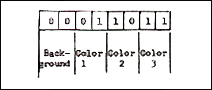
One way to use the DRAW and FILL routines is to use GR. 7 to create the screen display, then switch to GR. 8 to display it. When GR. 7 creates data for a colored pixel on the screen it uses two bits of display memory for each pixel. In Figure 1 the options available with four pairs of these bits are shown (0 means "off", 1 means "on"). Two bits together that are both "off" produce the background color, while any one or both bits of a pair that are "on" will produce color from one of the three color registers in GR. 7. When the GR. 7 display list fetches 40 bytes for display, with 8 bits per byte, it gets 320 bits. But since each pixel in GR. 7 requires two bits, GR. 7 only produces 160 pixels per line from the 320 bits per line in memory but each pixel can be one of four different colors.
When GR. 8 creates the display data it only stores one bit per pixel. When the GR. 8 display list gets 40 bytes of data it will produce the full 320 pixels per line with that data. Thus, with only one hit per pixel to work with, no color information can be included. A pixel is either on or off because a bit is either on or off. Thus, GR. 8 would interpret the data represented by Figure 1 one bit at a time and simply display a light or a dark pixel according to the status of each bit. But notice in Figure 1 that each pair of GR. 7 bits corresponds to either an even- or an odd-numbered pixel in GR. 8. Therefore GR. 8 would interpret the GR. 7 display data as artifact colors, just as it did the lines drawn on odd or even pixels in Listing 1. Each GR. 7 Color command corresponds to one of the GR. 8 artifact colors.
Listing 2. Drawing 3 Colors with GR. 7 for GR. 8 Display.
500 GRAPHICS 8:GRAPHICS 7:REM GR. 8 just clears out old garbage first
510 COLOR 1:PLOT 50,60:DRAWTO 50,30
520 DRAWTO 25,30:COLR=1:POSITION 25,60:GOSUB 580
530 COLOR 2:COLR=2:PLOT 100,60
540 DRAWTO 100,30:DRAWTO 70,30
550 POSITION 70,60:GOSUB 580
560 COLOR 3:COLR=3:PLOT 150,60
570 DRAWTO 150,30:DRAWTO 125,30:POSITION 125,60:GOSUB 580:GOTO 590
580 POKE 765,COLR:XIO 18,#6,0,0,"S:":RETURN
590 END
Let's draw a display with GR. 7 then change to GR. 8 without erasing the display. To do this we will simply add 32 to the Graphics mode number (e.g. GR. 8 + 32). Listing 2 will draw and fill three colors in GR. 7 (then we will add a line to change to GR. 8). Now, after examining the display, add the following line and run again.
590 GR. 8+32:SE. 2,0.0
Nobody is going to claim that this is of much use as it looks, but we have in fact used the DRAW and FILL routines to create four colors in GR. 7 that were interpreted as four artifact colors in GR. 8. If we could just clean up the trash and center the display we could draw the bottom half of a GR. 8 screen using the GR. 7 display memory and Basic Graphics statements.
Now, let's do it the other way around. The display data are sent to the screen by a special microprocessor called Antic. It knows where to find data, how much to send, and in which graphics mode because of the display list whose address is stored in memory at locations 560 and 561. The OS on the other hand puts the display data in memory. It knows where to put it because the screen memory address is stored in locations 88 and 89. It knows which graphics mode because the mode number is stored in memory at location 87. If we use the GR. 8 command to set up a Graphics 8 display list, Antic will fetch each line of memory and display it as GR. 8 data--each pixel either on or off, no color. If we POKE 87,7 the OS will put the display data into memory as GR. 7 data with the appropriate color bits set. This sounds exactly like the situation we encountered when explaining Figure 1, doesn't it? Add Listing 3 to Listing 2 to see this effect.
Listing 3.
Adding GR. 7 Data to Listing 2
590 IF J>0 THEN END
600 GR. 8+32
610 POKE 87,7
620 SE. 2,0,0:COLOR 1
630 J=1:GOTO 510
The end result is the same as before with one important exception; the display started at the upper left hand corner of the screen this time, and was therefore more controllable. Since the GR. 8 display list only generates one line of TV scan per pixel and GR. 7 data were created assuming there would be a GR. 7 display list to generate 2 lines per pixel, there were only enough data to fill the upper half of the screen. However, the bottom half was still filled with the data we generated before. Even though the bottom half still needs fixing, let's just observe this important point for the time being: it is possible to fill a Graphics 8 screen (i.e. use a GR. 8 display list) with Graphics 7 display data.
A More Useful DRAW for Graphics 7-Plus
Let's examine what happens when we run Listings 2 and 3. Graphics 8 requires 7680 bytes of display data. Graphics 7 only requires half that amount or 3840 bytes because its display list is supposed to tell Antic to generate twice as many display lines on the screen as Graphics 8 does. By setting up a Graphics 8 display using the GR. 8 command, 7680 bytes of memory are reserved for the display data. However, when we draw the display using the Poke to location 87, we are generating Graphics 7 display data in memory, so only 3840 bytes are stored in memory. The result is that the display only fills the upper half of the screen. How can we fill the remaining 3840 bytes? We did it earlier using the Graphics 7 to draw then switching to Graphics 8 without erasing the memory. Let's find a better way.
When we first set up a Graphics 8 display the OS reserves 7680 bytes of display memory. It also puts the location of the upper left screen corner data in memory locations 88 and 89 and in the display list. The OS then proceeds to consult locations 88 and 89 whenever it stores display data in memory, while Antic consults the display list when it retrieves data to display on the screen. Under standard conditions these two sets of screen data addresses are the same. However, if we were to set up a Graphics 8 display, then change memory locations 88 and 89 to show the address of the upper left corner of the screen to be 3840 bytes lower than the Graphics 8 screen corner, it should be possible to draw on the bottom half of the Graphics 8 screen since Antic still finds the corner of a display twice as big. Since the Graphics 8 display is twice as big as the Graphics 7 as far as memory is concerned, the effect of moving the display pointer for the Draw and Fill commands is to cause draw and fill to occur on the bottom half of the screen. To draw on the top half of the screen again, we simply Poke the original values back into locations 88 and 89.
Now, let's see if we can put it all together and draw a complete Graphics 8 screen with Graphics 7 data. We will set up a Graphics 8 display list with the GR. 8 command which will reserve 7680 bytes for display memory. Then we will tell the OS to put Graphics 7 data into that memory with a POKE 87,7 just as in listing 3. We will then proceed to draw the upper half of the screen display using Graphics 7 BASIC statements, then we will add 3840 bytes to the location of the upper left corner of the screen data and Poke this into locations 88 and 89. After that, the OS will think that the middle of the screen is the upper corner and will do any further drawing on the bottom half. Since the Graphics 8 display list was unchanged, Antic fetches display data from the original left corner all the time even though we change the locations for putting data into memory. Listing 4 is an example of this procedure. (Type NEW just to ensure that previous listings are erased.)
Listing 4. Drawing on Both Halves of a Graphics 7-Plus Screen.
10 DIM D88(1),D89(1)
20 ATOP=0:BOTTOM=1:GOTO 500
500 GR. 8+16:POKE 87,7
510 D88(ATOP)=PEEK(88):D89(ATOP)=PEEK(89)
520 BOTCORNER=D88(ATOP)+256*D89(ATOP)+3840
530 D89(BOTTOM)=INT(BOTCORNER/256)
540 D88(BOTTOM)=BOTCORNER-256*D89(BOTTOM)
550 DRAW=300:APLOT=300:FILL=400
560 SE. 2,0,0
570
580
590
Now continue the listing with these lines to draw on the screen.
600 COLOR 1:PLOT 0,0:DR. 79,95
610 COLOR 2:PLOT 159,0:DR. 79,95
620 COLOR 3:PLOT 79,0:DR. 79,95
630 POKE 88,D88(BOTTOM):POKE 89,D89(BOTTOM)
640 COLOR 1:PLOT 79,0:DR. 159,95
650 COLOR 2:PLOT 0,95:DR. 79,0
660 COLOR 3:PLOT 79,0:DR. 79,95
9999 GOTO 9999
Now, the only problem we have left is where to make the line segments coincide. (Notice that all PLOT, DRAW, and POSITION commands will be limited to the Graphics 7 cursor range of 0-159 horizontal by 0-95 vertical.) However, curved lines and diagonal lines that are off-center sound like the kind of dirty drudgery work a computer was made for. When it comes to matching the upper and lower half of the screen, why don't we just let the computer do our bookkeeping? Listing 5 (lines 200-350) will accomplish this bookkeeping (it also contains a repeat of Listing 4 for reference: lines 500-560). Do not run it yet, because some minor adjustments obviously must be made to draw and plot with it. To make these adjustments, add the following lines:
600 DEG:COLR=1
610 FOR I=0 TO 360 STEP 5
620 X=I/3:Y=80*SIN(I)+95
630 GOSUB DRAW
640 NEXT I
650 REM Just in case the old listing wasn't erased first
660
Now it is possible to draw lines all over the screen in a transparent manner with only minor adjustments to the normal PLOT and DRAW procedures. Instead of typing:
COLOR 1:X=1:Y=2:DRAWTO X,Y
We type (as a numbered line):
COLR=1:X=1:Y=2:GOSUB DRAW
Notice that it is not necessary to use APLOT on the very first point to be plotted. However, any time we wish to skip to a new location to continue drawing we simply type (again only as a numbered line):
X=1:Y=1:GOSUB APLOT
(APLOT and COLR are used because COLOR and PLOT are "reserved" words in Basic and will result in error messages.)
Let's try our original crossed lines with this new listing. Replace lines 600-640 as follows:
600 COLR=1:X=0:Y=0:GOSUB DRAW
610 X=159:Y=190:GOSUB DRAW
620 X=159:Y=0:COLR=2:GOSUB APLOT
630 X=0:Y=19O:GOSUB DRAW
640 COLR=3:X=79:Y=0:GOSUB APLOT
650 X=79:Y=190:GOSUB DRAW
9999 GOTO 9999
A detailed explanation of Lines 200-350 is a bit involved. Suffice it to say that any time a DRAW command crosses to a different half of the screen (upper or lower) the crossover point must be computed and the line must be drawn to the crossover point in the current screen half. Then the other half of the screen must be Poked into locations 88 and 89 after which the crossover point is PLOTted on the new half and the DRAW proceeds to its original destination. At no time is the value of Y for the PLOT and DRAW commands allowed to exceed 95.5, even though the computer operator is allowed to let Y range up to 191.
Just to check everything out, try adding these lines to the previous listing.
600 GOTO 1000
1000 DEC:J=1
1010 COLR=J
1020 FOR K=0 TO 315 STEP 45
1030 FOR I=0 TO 950 STEP 10
1040 Y=I*SIN(I-K)/13+95
1050 X=I*COS(I-K)/23+75
1060 IF I=0 THEN GOSUB APLOT:NEXT I
1070 GOSUB DRAW
1080 NEXT I
1090 J=J+1:IF J>3 THEN J=1
1100 COLR=J
1110 NEXT K
9999 GOTO 9999
Brief explanation of Listing 4:
Line 500 Sets up the Graphics 7-Plus display
Line 510 Finds the upper left screen corner used by the OS
Line 520 Converts the two bytes into a decimal value then adds 3840 to find the lower half's upper corner
Lines 530-540 Convert the decimal value for the lower half into a low byte and a high byte
Lines 570-590 Just in case you did not type NEW
Lines 600-620 Draw on the upper half (Cursor range--159X95)
Line 630 Pokes the lower half into OS memory
Lines 640 to 660 draw the lower half (Cursor range--159X95)
Line 9999 is necessary because we used the whole screen option in line 500
FILLING in Graphics 7-Plus
"So, what good are lines?" you ask, "I want color-filled areas." As you might expect the previously explained techniques can be extended to provide a semi-transparent FILL command. Notice the weasel-word qualifier on "transparent." As you are probably aware, FILL (i.e. XIO 18,#6,0,0,"S:") only works according to rules established on some level of thought other than our own. When we try to make it behave predictably under ordinary circumstances we can expect some difficulty, let alone when trying to draw on two different screens (or halves of screens) at once. So, with that caveat let us proceed.
Listing 6 shows lines to add to listing 5 in order to make FILL cross screen halves in Graphics 7-Plus. Again a detailed explanation would expend a lot of words just to say that we must compute the crossover points in between the two halves of the screen, fill to them, Poke the other half of the screen into memory at locations 88 and 89, then fill on the remaining half. Most of the tests are simply to keep the cursor within range under a variety of combinations of possibilities.
In this case, we gained some convenience, however, which will help make up for the FILL glitches that crop up from time to time. POSITION and the POKE to 765 are now automatic and XIO has been replaced.
To use the FILL command you must first draw the right and upper sides using the GOSUB DRAW and GOSUB APLOT method as before. Then, instead of typing
POS. 0,159:POKE 765,1:XIO 18,#6,0,0,"S:"
we simply type (as a numbered line)
X=0:Y=159:GOSUB FILL
The color will be the last value assigned to COLR and the X and Y values must be the lower left corner of the area to be filled. Add these lines to the previous listing to observe the fill in operation.
600 SE. 2,0,0:COLR=1
610 X=159:Y=190:APLOT
620 X=159:Y=0:GOSUB DRAW
630 X=0:Y=0:GOSUB DRAW
640 X=159:Y=190:GOSUB FILL
650 X=0:Y=190:COLR=2:GOSUB APLOT
660 X=78:Y=95:GOSUB DRAW
670 X=0:Y=1:GOSUB DRAW:X=0:Y=190:GOSUB FILL
680 COLR=3:X=158:Y=190:GOSUB APLOT
690 X=79:Y=96:GOSUB DRAW
700 X=0:Y=190:GOSUB FILL
710 GOTO 710
Listing 5: Plot and Draw Subroutines for Graphics 7-Plus.
10 DIM D88(1),D89(1),QX(1),XFLAG(1):XFLAG(0)=0:XFLAG(1)=0
198 GOTO 500
199 REM ****DRAW SUBROUTINE****
200 COLOR COLR:QX3=X:QY3=Y:Y=INT(QY3+0.5)
205 IF Y>95.5 THEN QN=1:IF QY1<95.5 THEN QN=0:GOTO 225
210 IF Y<95.5 THEN QN=0:IF QY1>95.5 TNEN QN=1:GOTO 225
215 DRAWTO X,Y-96*QN:QX1=X:QY1=Y
220 RETURN
225 QX2=X:QY2=Y
230 GOSUB 265:X=INT(X+0.5):GOSUB 280
235 DRAWTO X,Y-96*QN:QN=1-QN
240 POKE 88,D88(QN):POKE 89,D89(QN)
245 GOSUB 265:X=INT(X+0.5)
250 PLOT X,95-95*QN
255 DRAWTO QX2,QY2-96*QN
260 QX1=QX2:QY1=QY2:X=QX3:Y=QY3:RETURN
265 Y=95:QN=((Y-QY1)*(QX2-QX1)/(QY2-QY1))+QX1
270 IF ABS(QY2-QY1)=1 THEN X=(QX2+QX1)/2
275 RETURN
280 IF XFLAG(QM)=0 THEN XFLAG(QM)=1:QX(QM)=X:QM=1-QM:XFLAG(QM)=0
285 RETURN
299 REM ****APLOT SUBROUTINE****
300 COLOR COLR:QX3=X:QY3=Y:Y=INT(QY3+0.5)
310 IF Y>95.5 THEN QN=1:GOTO 330
320 QN=0
330 POKE 88,D88(QN):POKE 89,D89(QN)
340 PLOT X,Y-QN*96:QX1=X:QY1=Y:DRAW=200:X=QX3:Y=QY3
350 RETURN
499 REM ****SET UP GR.7+ SUBROUTINE***
500 GRAPHICS 8+16:POKE 87,7
510 D88(0)=PEEK(88):D89(0)=PEEK(89)
520 DISP2=D88(0)+256*D89(0)+3840
530 D89(1)=INT(DISP2/256)
540 D88(1)=DISP2-256*D89(1)
550 DRAW=300:APLOT=300:FILL=400
560 SETCOLOR 2,0,0:COLOR 1:COLR=1
The background color can be produced in the same manner as the other three colors. It is important that the only COLOR specifications be made with the COLR= statement from this point on in using the listings.
To experiment with how the different colors look when plotted on one another, remove Line 710 and (if you left lines 1000-9999 in from the previous listings) observe how the spiral behaves as it crosses the different fill areas. Also, change Line 1010 (1010 COLR=0).
Five Colors?
Yes, you saw it, too, a fifth color (counting background) appeared when colors 1 and 2 were plotted close together. Anytime Color 2 is drawn to the immediate right of Color 1, a fifth color will appear unless the line drawn is horizontal. Such knowledge could be used to add another color in limited amounts, or it could be just another bug to look for, depending on your project.
So there you have it; Graphics 7-Plus in Basic. The program listing to set it up is but 48 short lines of Basic, and the method for using it is similar to the use of PLOT and DRAWTO in any other Basic program. A bonus is that FILL works in a more transparent manner even though the usual FILL idiosyncrasies are a little more annoying with artifact colors.
This is but one more example of how the built-in flexibility of the Atari makes it possible to extend the application into areas beyond the limits of the original software design. If playing with this introduction to artifacting with Graphics 7-Plus has been enlightening, perhaps you may be able to use it. If the inherent bugs are too frustrating then you might try some language other than Basic that does not rely so heavily on the existing OS DRAW and FILL routines. Either way, happy artifacting.
Listing 6: Lines to Add to Listing 5 for FILL Subroutine.
399 REM ****FILL SUBROUTINE****
400 POKE 765,COLR:QX3=X:QY3=Y:Y=INT(QY3+0.5)
405 IF Y>95.5 THEN ON1:IF QY1<95.5 THEN QN=0:GOTO 435
410 IF Y<95.5 THEN QN=0:IF QY1>95.5 THEN QN=1:GOTO 435
415 POSITION X,Y-96*QN:XIO 18,#6,0,0,"S:":QX1=X:QY1=Y
420 IF FLAG THEN FLAG=0:RETURN
425 XFLAG(0)=0:XFLAG(1)=0:X=QX3:Y=QY3
430 RETURN
435 QX2=X:QY2=Y:GOSUB 265:FLAG=1:GOSUB 415
440 QN=1-QN:X=INT(X+0.5)
445 POKE 88,D88(QN):POKE 89,D89(QN)
450 GOSUB 265:X=INT(X+0.5)
455 Y=QY2:GOSUB 280
460 X=QX2:IF XFLAG(1-QM)=0 THEN QX(1-QM)=((95-QY1)*(X-QX1)/(Y-QY1))+QX1:XFLAG(1-QM)=1
465 PLOT QX(QM),95-95*QN:DRAWTO QX(1-QM),95-95*QN
470 GOTO 415
|
||||||||||||||||
|
Table 1. Some Artifact Colors. |
Harry G. Arnold, 109 Newhaven Road, Oak Ridge, TN 37830.
Table of Contents
Previous Section: The Atari Graphics Composer
Next Section: Bits & Bytes